DIAGNOSTICS
Vertical Express Product Manual 3-9 88500 v.1.0
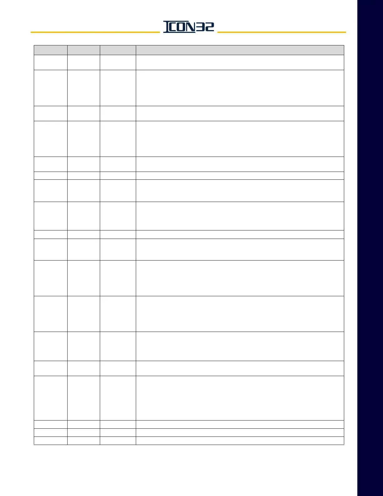
Diagnostics Section Adjustments
This manual shows only the parameters that have an operational relevance to the ICON32. The UIT may have
additional parameters available, which should not effect the controller operation.
H17 floor 1–nf
Flooded Pit Sensor 1 Operation Return Floor - This adjustment sets the floor that the car
goes to if the pit is flooded, sensor input FPS1.
H18 F/R 0–1
Flooded Pit Sensor 1 Operation Return Door - This adjustment sets the side of doors that
cycle upon arrival at the return floor during Flooded Pit Operation, sensor input FPS1.
Values:
0 = Front
1 = Rear
H19 floor 1–nf
Flooded Pit Sensor 2 Operation Return Floor - This adjustment sets the floor that the car
goes to if the pit is flooded, sensor input FPS2.
H20 F/R 0–1
Flooded Pit Sensor 2 Operation Return Door - This adjustment sets the side of doors that
cycle upon arrival at the return floor during Flooded Pit Operation, sensor input FPS2.
Values:
0 = Front
1 = Rear
H21 sec. 0-30
Flooded Pit Door Open Time - This adjustment sets the door standing time used at the
return floor.
J10 pounds 500–65000 Capacity - The rated car capacity.
J11 — 1–# of cars
Car ID - The car number within a group, beginning with 1. Used by the software for identi-
fication and I/O assignments. See ELD for the designator - used by programs and people
for identification. Note: Altering this value may cause some features to malfunction.
J12 — 0–240
Car Communication Number.
Values:
0 = The controller computes the comm number from the car and group number.
1-255 = Force to the selected comm number.
J13 — 1–8 Group ID - The group number within a multiple group network, beginning with 1.
J14 floor 1–nf
Lobby Floor - This adjustment sets the lobby to the proper car opening (beginning with 1 =
bottom floor).
Note: This floor number may not be the building floor number.
J19 — 0–1
Relevel on the Stop Switch - Permits a re-level with the in Car Stop Switch active and the
CST input not active; Does not permit a re-level for the Fireman's Stop Switch(es).
Values:
0 = No releveling while the Emergency Stop Switch is thrown.
1 = Up releveling only while Emergency Stop Switch is thrown.
J20 — 0–1
Stop Switch Type - This adjustment sets the value to the type of stop switch provided on
this installation.
Values:
0 = Keyed stop switch.
1 = Public access stop switch.
L10 cars 0–ncars
Lobby Elevator Request - Number of cars requested to park at the lobby.
Values:
0 = Disable
1 = Enable
L12 floors 1–nfloors
Lobby - This adjustment sets the designated floor position number for the lobby floor, and
is also used as the homing floor for the lobby elevator request.
L14 floors 1–nfloors
Zone 1 Floor - The car stays at the last floor served for normal operation.
Notes:
• When parking is enabled and a car becomes free, it will be sent to one of the zone floors
(after a time delay - L25).
• L14 through L19 allow for six different zone or parking floors.
• The number of zone floors used is set by L20.
L15 floors 1–nfloors Zone 2 Floor - See L14.
L16 floors 1–nfloors Zone 3 Floor - See L14.
L17 floors 1–nfloors Zone 4 Floor - See L14.
Adj (cont.) Unit Range Definition (cont.)