• Use the following instructions to set up the mapping of each digital input or analog sensor
input to each relay.
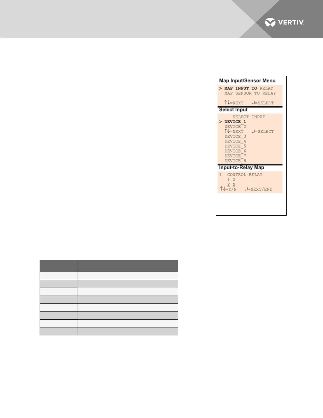
7.11.1 Set Up Mapping for a Digital Input
• Use the arrows to choose Map Input To Relay from the Map
Input/Sensor Menu, and press Enter.
• From the Select Input Menu, choose the input you want—for
example, Device_1—and press Enter.
• On the Input-to-Relay Map screen, you may map the selected
input to either or both of the control relays (1-2). The example at
right shows Device_1 mapped to Control Relay1.
To make changes to the mapping:
• If needed, press Enter to advance to the position directly
below the relay.
• Use the arrows to choose Y (Yes - Mapped to this relay) or
N (No - Not mapped), then press Enter.
• Press Enter to advance to the next position where you
want to make a change.
• Use the arrows to choose Y (Yes - Mapped to this relay) or
N (No - Not mapped), then press Enter.
• When finished, press Enter again.
Default Mappings - Digital Inputs to Control Relays
By default, digital inputs are not mapped to any control relay, as shown in Table 7.17 below.
Digital input By default, mapped to control relay:
Device_1 (none)
Device_2 (none)
Device_3 (none)
Device_4 (none)
Device_5 (none)
Device_6 (none)
Device_7 (none)
Device_8 (none)
Table 7.17
Default mapping of digital inputs to relays
Vertiv | Liebert® AC8 User Manual | 102