Item Description For more information, see:
Y - Power On/Off
switch (Transformer
Module)
Power switch to turn power On/Off to both Transformer Module
24VAC connectors and power receptacle.
Termination and Mounting on
page15
3.0: Wiring and Connections
Z - 24VAC connector
(Transformer Module)
One of the two 24VAC connectors for power (the second is also on
the right side of the Transformer Module near the top). Each
connector is rated for 40VA.
Termination and Mounting on
page15
3.0: Wiring and Connections
AA - Modem
On-board modem with 9600 baud rate.
Setup System - Setup Modem
& Pagers on page72
BB - Modem status
LEDs
Indicates the operational status of the modem. LED Indicators below
CC - DIP switch 1
DIP switch used for resetting password to default.
Change Password on
page83
DD - LCD connector
Connection for the LCD on the enclosure door. N/A
EE - LCD contrast
adjustment
Adjustment contrast for the LCD on the enclosure door. N/A
FF - Battery pack
connector
Connection for battery pack lead.
Connecting the Battery Pack
on page16
GG - 24VAC power
connector
Power connection for the controller. Requires 24VAC.
Connect Power to the Liebert
AC8 on page14
HH - Transformer
Module
Transformer Module used to convert 115VAC or 230VAC to
24VAC.
Termination and Mounting on
page15
Table 1.1 Controller board components (continued)
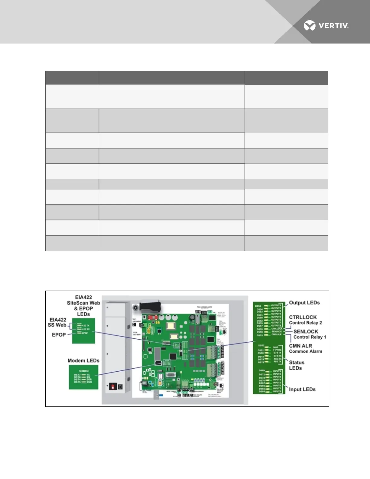
1.8 LED Indicators
The Liebert AC8 controller board has LED indicators that show the status of inputs, outputs and the
common alarm, as well as the modem, Liebert® SiteScan Web™ and EPOP connections.
Vertiv | Liebert® AC8 User Manual | 8