Appendix B: Default Settings Quick Reference Guide
This appendix provides a quick reference to default settings for the Liebert AC8. These settings also
appear throughout the manual.
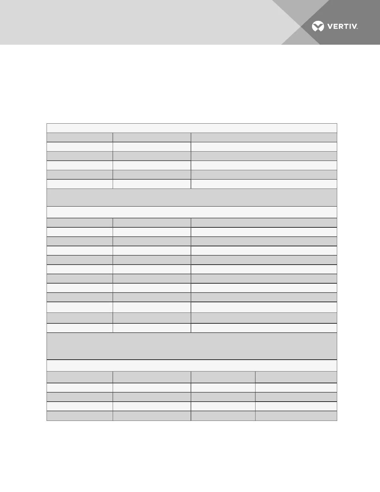
DEFAULT SETTINGS - DIGITAL INPUTS (FROM Table 7.2 on page57)
Feature Default Other Options
LABEL DEVICE_1 - DEVICE_8 Any name (up to eight characters)
NORM OPEN/CLOSE NO (Normally open) NC (Normally closed)
ALARM/EVENT AL (Alarmable) EV (Event)
LATCHED L (Latched) / Y (Yes)* NL (Unlatched) / N (No)*
DELAY 00:01 (1 second) Any time (in minutes and seconds) from 00:00 to 99:59
* NOTE: Different abbreviations are used to designate a digital input as Latched (L/Y) or Unlatched (NL/N) in Select Input/Set Inputs
screens.
DEFAULT SETTINGS - ANALOG SENSOR INPUTS (FROM TABLE 7.4 ON PAGE62)
Feature Default Other Options
CONNECTED* N (Not connected)* Y (Connected)**
LABEL SENSOR_1 - SENSOR_4 Any name (up to eight characters)
UNITS DEG Any units (up to three characters)
4 mA +045.0 Can define up to two decimal places—e.g., -99.99
20 mA +096.0 Can define up to two decimal places—e.g., +99.99
OFFSET +000.0 Can define up to two decimal places—e.g., +00.00
ALARM/EVENT AL (Alarmable) EV (Event)
LATCHED N (Unlatched) Y (Latched)
LOW SETPT
+0050.0
Can define up to two decimal places—e.g., -999.99
HIGH SETPT
+0090.0
Can define up to two decimal places—e.g., +999.99
SENSOR DELAY 00:01 (1 second) Any time (in minutes and seconds) from 00:00 to 99:59
* If a sensor is configured as N (Not connected), the display will show an empty reading (blank spaces).
** If a sensor is configured as Y (Connected) and is functioning properly, the display will show a reading.
If the connected sensor is not functioning properly, the display will show dashes (------) indicating a problem.
DEFAULT MAPPINGS - DIGITAL INPUTS TO CONTROL RELAYS (FROM TABLE 7.17 ON PAGE102)
Digital input
Mapping to control relay:
Digital input
Mapping to control relay:
Device_1 (none) Device_5 (none)
Device_2 (none) Device_6 (none)
Device_3 (none) Device_7 (none)
Device_4 (none) Device_8 (none)
Table B.1
Liebert AC8 - default settings for inputs and outputs
Vertiv | Liebert® AC8 User Manual | 163