2.4.1 Termination and Mounting
WARNING! Be sure that the Power On/Off switch is set to OFF before installing any wiring to
this unit. The switch is at the bottom of the unit.
Input Power Connections
To connect electrical power to the Transformer Module:
1. Install electrical wiring from utility power to the Transformer Module.
2. Use copper wires only; proper wiring to use for power is 14/2 AWG copper wire with ground.
3. For the TM230 only: strip wires 3/8" (9.6mm).
Note: For the TM115, wires are pre-stripped 0.4" (10.2mm) at the factory.
4. Connect the wiring as follows:
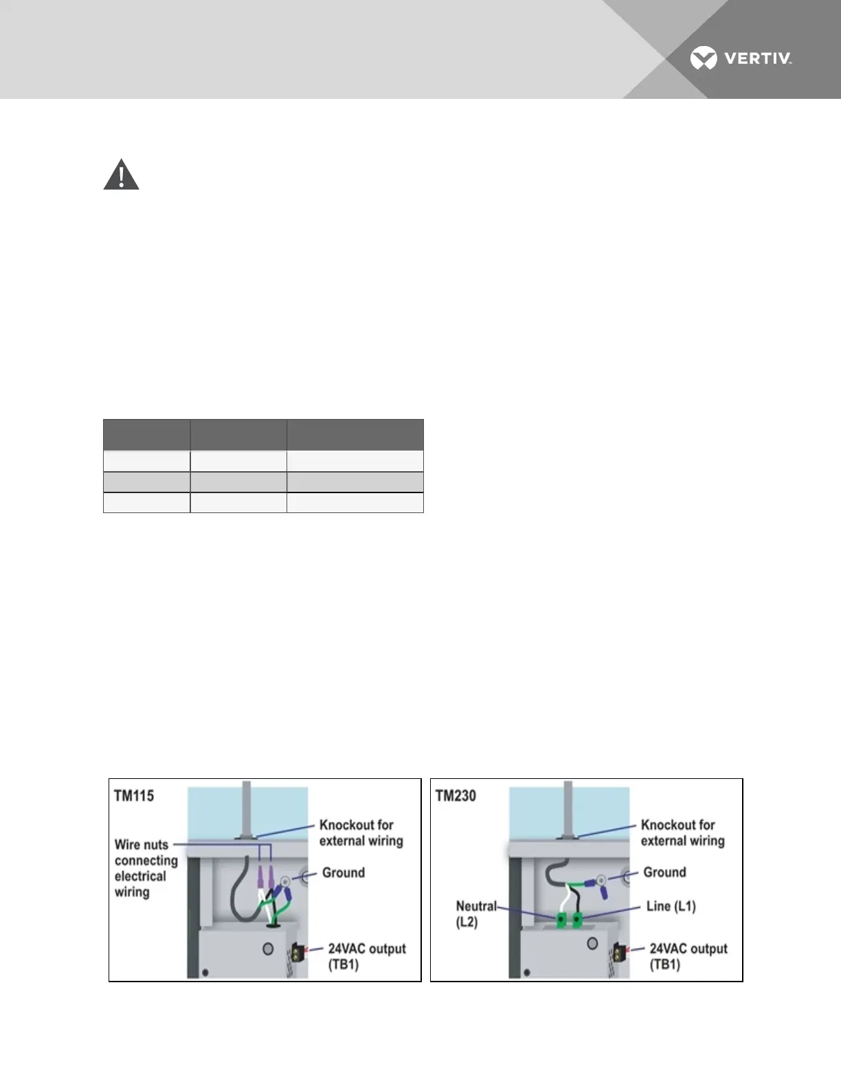
TM115 TM230 Connection Type
White wire Neutral (L2) Neutral
Black wire Line (L1) Power (Line)
Green wire Ground lead Ground
5. Secure the incoming electrical service wires to the TM115 input wires with wire nuts as shown in
Figure 2.2 below or to the TM230 connectors as shown in Figure 2.3 below.
24 VAC Output Power Connections
To connect to the 24VAC outputs:
1. Install electrical wiring from device requiring 24VAC power to the Transformer Module.
2. Use copper wire only; proper wiring to use for power is 18, 20 or 22 AWG copper wire. Strip
wire 1/4".
3. There are two 24 VAC output connectors (TB1 and TB2). Terminate wires to the connector as
shown in Figure 2.2 below andFigure 2.3 below. TB1 and TB2 are NOT polarity sensitive.
4. Secure the wires to the connector.
Figure 2.2 Power wiring to TM115 Figure 2.3 Power wiring to TM230
Vertiv | Liebert® AC8 User Manual | 15