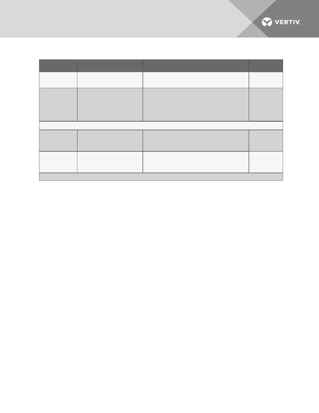
Connection Supported Wire Type Maximum Wire Length Rating
Phone/Modem
Line
4 Wire (Pins 3 & 4)
RJ11 Connector
N/A N/A
24VAC Power
Connection
(TB7)
18-22 AWG Stranded &
Shielded
18 AWG* (recommended)
Non Plenum - Belden 8770
Plenum - Belden 88770
150 ft. (45m)
24VAC
@1.3A
Power Connections (Transformer Module)
115VAC
14 AWG Stranded &
Unshielded
Non Plenum - Belden 5101UE
150 ft. (45m)
115VAC
@4A
230VAC
14 AWG Stranded &
Unshielded
Non Plenum - Belden 5101UE
150 ft. (45m)
230VAC
@0.5A
* Recommended
Table 3.1 Wiring specifications (continued)
3.2 Connecting Digital Inputs and Digital Outputs
The digital inputs, digital outputs and control relay outputs are found on the right side of the Liebert
AC8’s printed wiring assembly board. Each set has two terminal blocks—one green, the other black:
• Digital inputs: two terminal blocks, with four inputs per block (8 inputs total)
• Digital outputs: two terminal blocks, with four outputs per block (8 outputs total)
• Control relay outputs: two terminal blocks, with one output per block (2 outputs total)
Each input is tied to an output with the same number:
• Input 1 is tied to Output 1 (default name: Device_1)
• Input 2 is tied to Output 2 (default name: Device_2)
• Input 3 is tied to Output 3 (default name: Device_3)
.
.
.
• Input 8 is tied to Output 8 (default name: Device_8)
Up to eight devices may be connected to the Liebert AC8. Each device must be connected to an input
and an output with the same number.
To determine the proper wire size, see Wiring and Connections on page17.
NOTE: Each terminal block is a removable, two-part assembly to permit easier connection of more than
one input at a time. If making multiple connections, grasp the upper portion of a block and pull firmly to
the right until the assembly pulls apart.
After making the connections, push the removed piece back into the portion attached to the printed
wiring assembly until the terminal block pieces lock together.
Vertiv | Liebert® AC8 User Manual | 19