104 • Step-by-Step Guide to your own Linux Application
Setting the IP address of the Linux Fieldbus Coupler
WAGO-I/O-SYSTEM 750
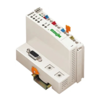
Linux Fieldbus Coupler
5.5 Setting the IP address of the Linux Fieldbus Coupler
The Linux fieldbus coupler has the factory-set IP address . If you want another
address or dynamic address assignment, the configuration is done via the serial
interface of the Linux fieldbus coupler. Connect the serial interface (COM
port) to the configuration interface of the Linux fieldbus coupler using the
communication cable (750-920).
In order to set the configuration of the new IP address a terminal program
must be used to communicate between the two devices. This can be minicom
under Linux, or Hyperterminal.exe under Windows. The terminal program
should be configured with the parameters 38400-8-N-1-NoFlowControl.
A volatile IP adress can then be assigned in the console, e.g.
> ifconfig eth0 192.168.1.4 (sets temporary IP address)
Please use the wagoset program for a permanent configuration of the Ethernet
interface. This program writes the settings to the flash memory of the Linux
coupler. In this way the settings are also available after the next start-up.
> wagoset –i 192.168.1.8 (sets permanent IP address)
Dynamic IP address assignment via DHCP for the next start of the Linux
filedbus coupler can be set as follows:
> wagoset –m dhcp

 Loading...


