EasyManuals Logo

WAGO 750 Series User Manual

WAGO 750 Series
248 pages
To Next Page IconTo Next Page
To Previous Page IconTo Previous Page
Page #45 background imageLoading...
Page #45 background image
The WAGO-I/O-SYSTEM 750 41
Assembly Guidelines/Standards
WAGO-I/O-SYSTEM 750
Linux Fieldbus Coupler
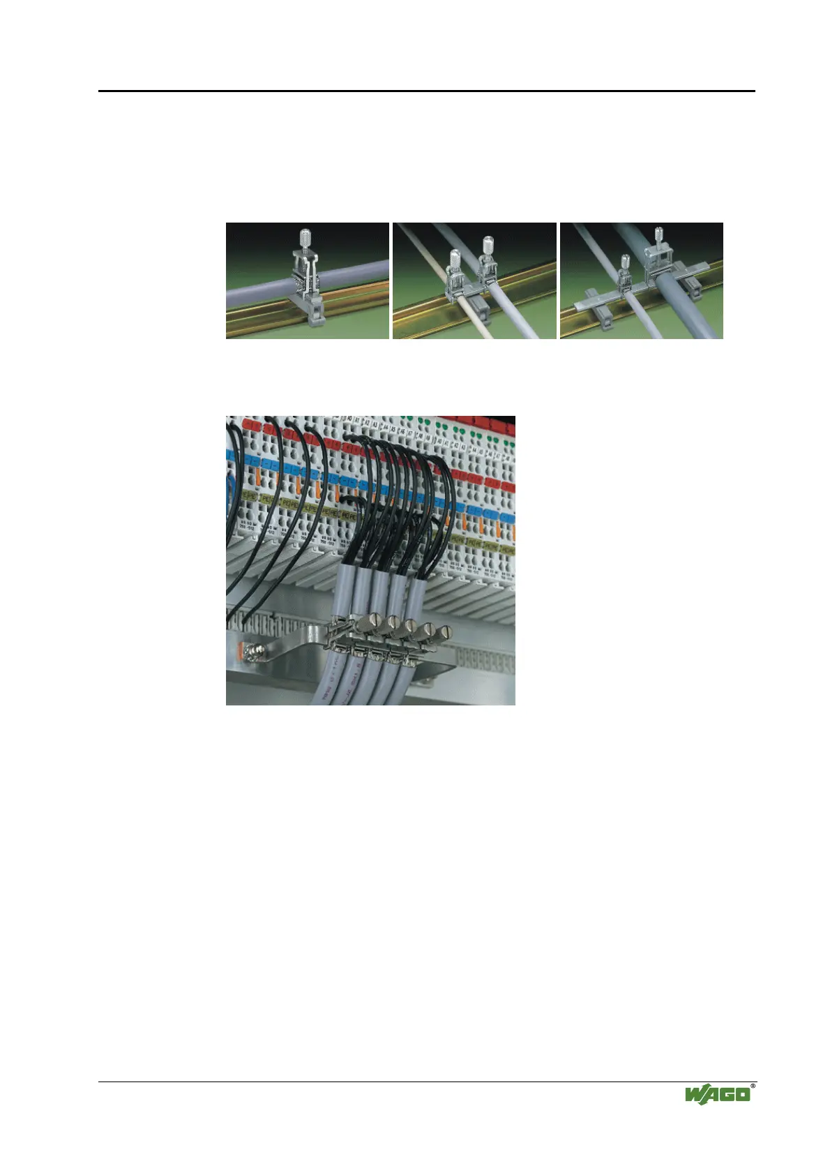
2.9.4 WAGO Shield (Screen) Connecting System
The WAGO Shield Connecting system includes a shield clamping saddle, a
collection of rails and a variety of mounting feet. Together these allow many
different possibilities. See catalog W4 volume 3 chapter 10.
Fig. 2-25: WAGO Shield (Screen) Connecting System p0xxx08x, p0xxx09x, and p0xxx10x
Fig. 2-26: Application of the WAGO Shield (Screen) Connecting System p0xxx11x
2.10 Assembly Guidelines/Standards
DIN 60204, Electrical equipping of machines
DIN EN 50178 Equipping of high-voltage systems with electronic
components (replacement for VDE 0160)
EN 60439 Low voltage – switch box combinations

Table of Contents

Other manuals for WAGO 750 Series

Questions and Answers:

Question and Answer IconNeed help?

Do you have a question about the WAGO 750 Series and is the answer not in the manual?

WAGO 750 Series Specifications

General IconGeneral
Protection ClassIP20
Bus CouplersPROFIBUS, CANopen, Ethernet
ModulesDigital Input, Digital Output, Analog Input, Analog Output
MountingDIN rail mounting
Voltage Supply24 V DC (typical)
Communication ProtocolDepends on the bus coupler (e.g., PROFIBUS, CANopen, DeviceNet, Ethernet)
Digital Input ChannelsVaries by module (e.g., 8, 16 channels)
Digital Output ChannelsVaries by module (e.g., 8, 16 channels)
Analog Input ChannelsVaries by module (e.g., 2, 4, 8 channels)
Analog Output Channels1, 2, 4 channels (depending on module)
Width12 mm, 24 mm (typical module widths)
Number of ChannelsVaries by module type
Current Consumption per ChannelVaries by module type

Related product manuals