Use in Hazardous Environments • 223
Classification Meeting CENELEC and IEC
WAGO-I/O-SYSTEM 750
Linux Fieldbus Coupler
11.3.5 Types of Ignition Protection
Ignition protection defines the special measures to be taken for electrical
components in order to prevent the ignition of surrounding explosive
atmospheres. For this reason a differentiation is made between the following
types of ignition protection:
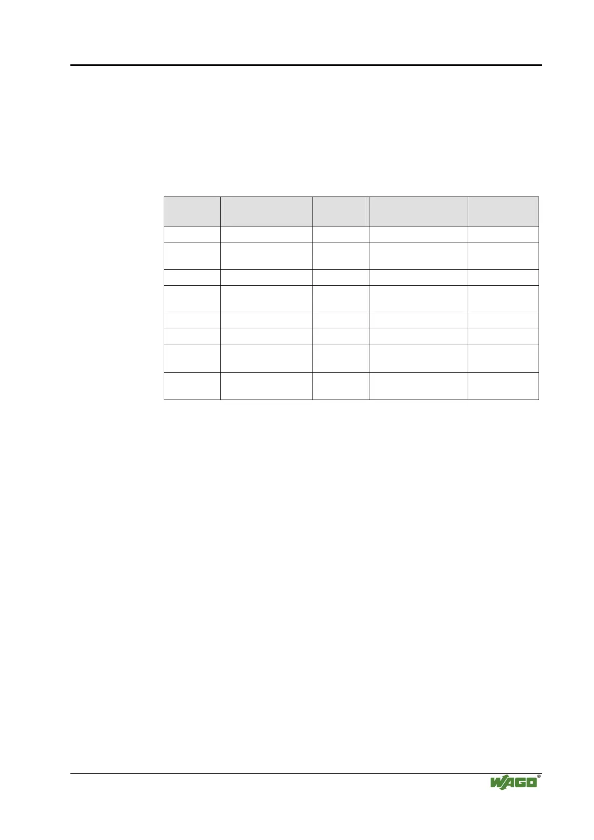
Tab. 11-5: Types of Ignition Protection
Identifi-
cation
CENELEC
standard
IEC
standard
Explanation Application
EEx o EN 50 015 IEC 79-6 Oil encapsulation Zone 1 + 2
EEx p EN 50 016 IEC 79-2
Overpressure
encapsulation
Zone 1 + 2
EEx q EN 50 017 IEC 79-5 Sand encapsulation Zone 1 + 2
EEx d EN 50 018 IEC 79-1
Pressure resistant
encapsulation
Zone 1 + 2
EEx e EN 50 019 IEC 79-7 Increased safety Zone 1 + 2
EEx m EN 50 028 IEC 79-18 Cast encapsulation Zone 1 + 2
EEx i
EN 50 020 (unit)
EN 50 039 (system)
IEC 79-11 Intrinsic safety Zone 0 + 1 + 2
EEx n EN 50 021 IEC 79-15
Electrical components
for zone 2 (see below)
Zone 2
Ignition protection “n" describes exclusively the use of explosion protected
electrical components in zone 2. This zone encompasses areas where
explosive atmospheres can only be expected to occur rarely or short-term. It
represents the transition between the area of zone 1, which requires an
explosion protection and safe area in which for instance welding is allowed at
any time.
Regulations covering these electrical components are being prepared on a
world-wide scale. The standard EN 50 021 allows electrical component
manufacturers to obtain certificates from the corresponding authorities for
instance KEMA in the Netherlands or the PTB in Germany, certifying that the
tested components meet the above mentioned standards draft.
Type “n” ignition protection additionally requires electrical components to be
marked with the following extended identification:
• A – non spark generating (function modules without relay /without
switches)
• AC – spark generating, contacts protected by seals (function
modules with relays / without switches)
• L – limited energy (function modules with switch)

 Loading...


