Use in Hazardous Environments • 227
Identification
WAGO-I/O-SYSTEM 750
Linux Fieldbus Coupler
11.5.2 For America
According to NEC 500
Hansastr. 27
D-32423 Minden
ITEM-NO.:750-400
2DI 24V DC 3.0ms
0.08-2.5mm
2
0V 24V DI1
Di2
PATENTS PENDING
II3G
KEMA 01ATEX1024 X
EEx nA II T4
CL I DIV 2
Grp. A B C D
op temp code T4A
24V DC
AWG 28-14
55°C max ambient
24246
4100--02----03
LISTED 22ZA AND 22XM
CL I DIV 2
Grp. ABCD
optemp code T4A
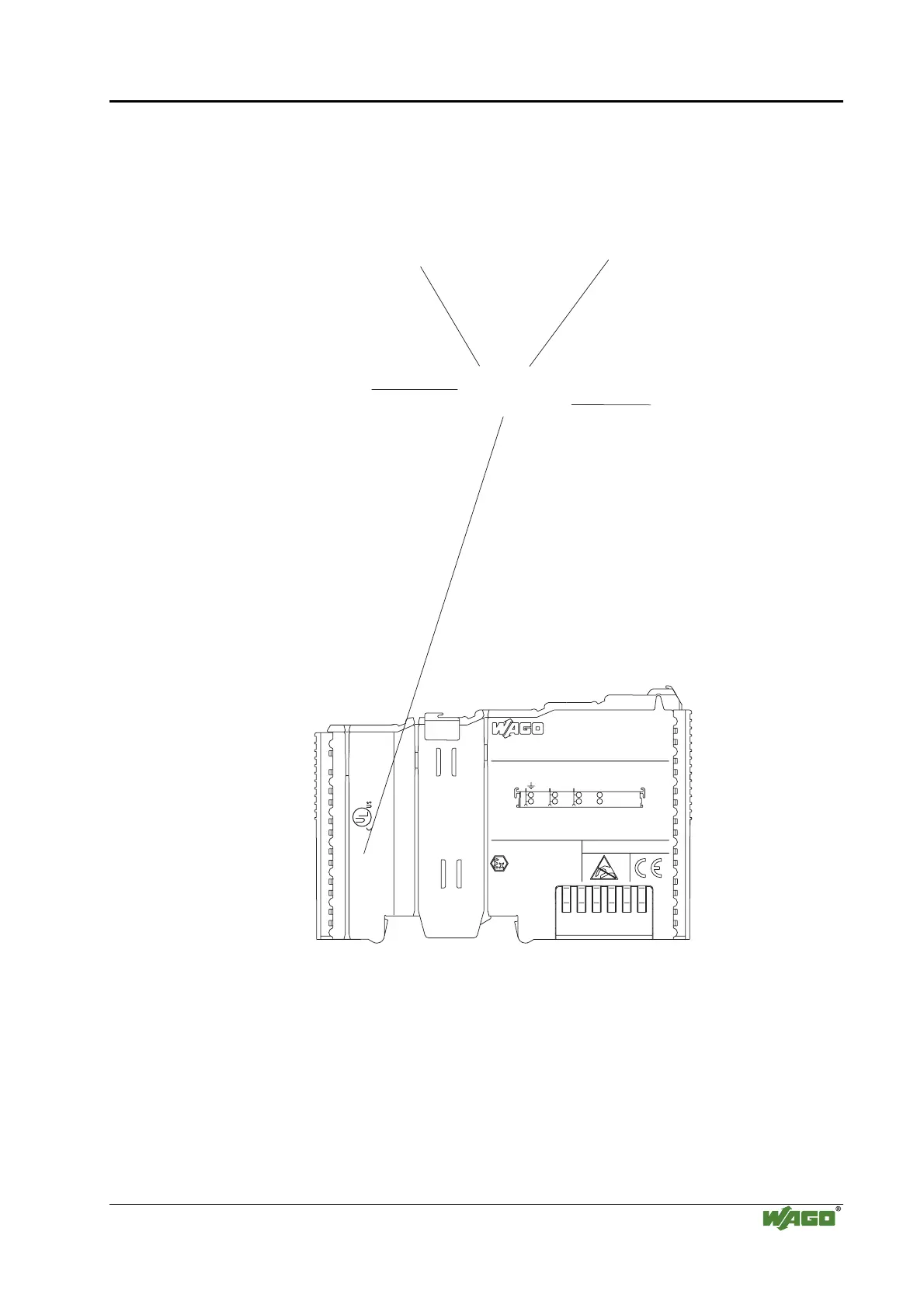
Explosion group
(gas group)
Explosion protection group
(condition of use category)
Area of application (zone)
Temperature class
Fig. 11.5.2-1: Example for lateral labeling of bus modules
(750-400, 2 channel digital input module 24 V DC)
g01xx04e

 Loading...


