The WAGO-I/O-SYSTEM 750 • 27
Power Supply
WAGO-I/O-SYSTEM 750
Linux Fieldbus Coupler
2.7.2 System Supply
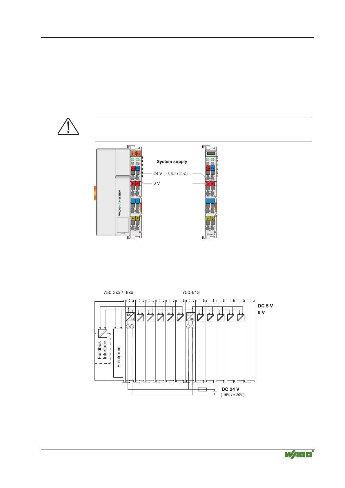
2.7.2.1 Connection
The WAGO-I/O-SYSTEM 750 requires a 24 V direct current system supply
(-15% or +20 %). The power supply is provided via the coupler/controller and,
if necessary, in addition via the internal system supply modules (750-613).
The voltage supply is reverse voltage protected.
Attention
The use of an incorrect supply voltage or frequency can cause severe damage
to the component.
Fig. 2-11: System Supply g0xxx02e
The direct current supplies all internal system components, e.g.
coupler/controller electronics, field bus interface and bus modules via the
internal bus (5 V system voltage). The 5 V system voltage is electrically
connected to the 24 V system supply.
Fig. 2-12: System Voltage g0xxx06e

 Loading...


