36 • The WAGO-I/O-SYSTEM 750
Power Supply
WAGO-I/O-SYSTEM 750
Linux Fieldbus Coupler
2.7.6 Power Supply Unit
The WAGO-I/O-SYSTEM 750 requires a 24 V direct current system supply
with a maximum deviation of -15% or +20 %.
Recommendation
A stable network supply cannot be taken for granted always and everywhere.
Therefore, regulated power supply units should be used in order to guarantee
the quality of the supply voltage.
A buffer (200 µF per 1 A current load) should be provided for brief voltage
dips. The I/O system buffers for approx 1 ms.
The electrical requirement for the field supply is to be determined individually
for each power supply point. Thereby all loads through the field devices and
bus modules should be considered. The field supply as well influences the bus
modules, as the inputs and outputs of some bus modules require the voltage of
the field supply.
Note
The system supply and the field supply should be isolated from the power
supplies in order to ensure bus operation in the event of short circuits on the
actuator side.
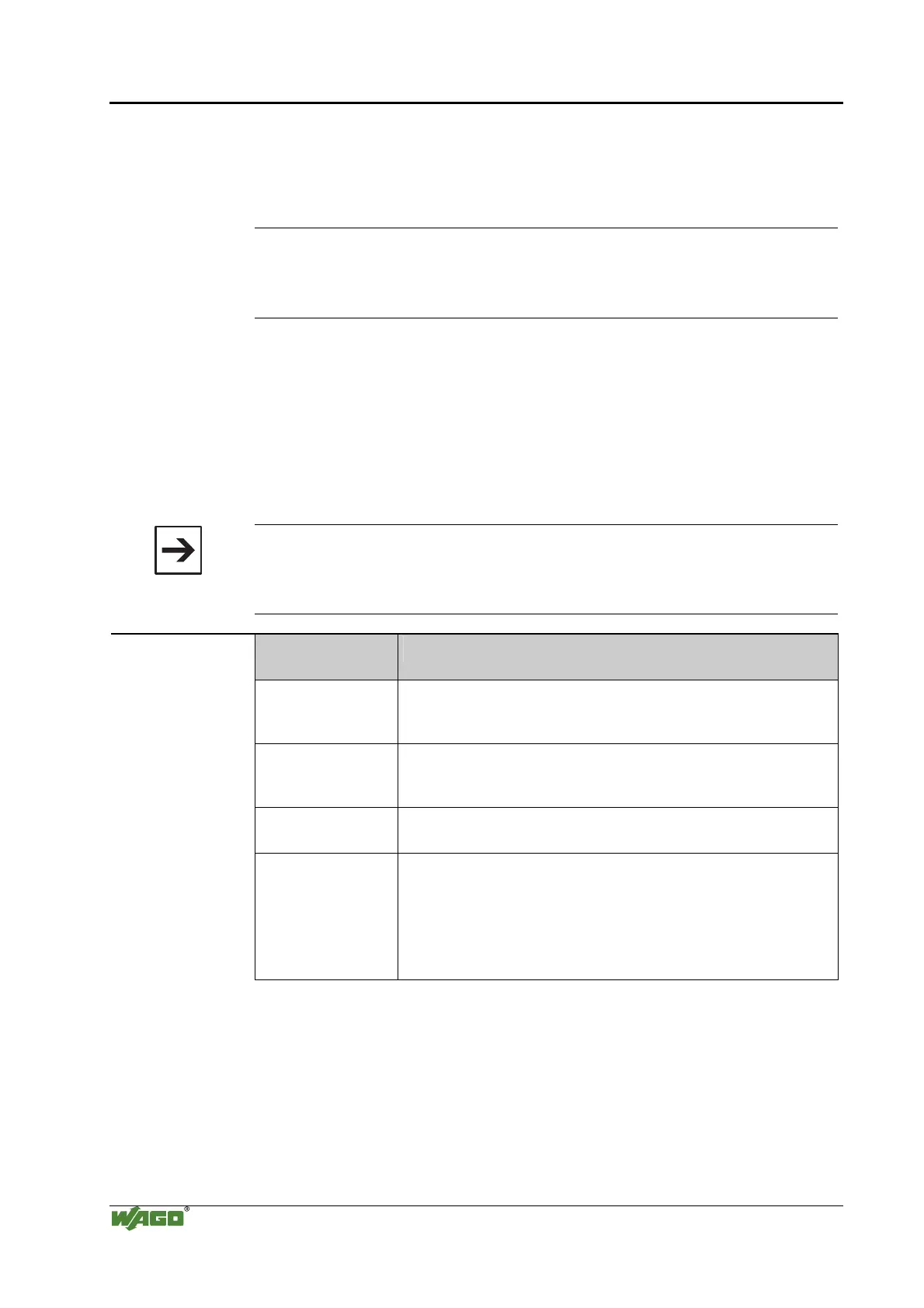
WAGO products
Item No.
Description
787-903 Primary switched-mode, DC 24 V, 5 A
wide input voltage range AC 85-264 V
PFC (Power Factor Correction)
787-904 Primary switched-mode, DC 24 V, 10 A
wide input voltage range AC 85-264 V
PFC (Power Factor Correction)
787-912 Primary switched-mode, DC 24 V, 2 A
wide input voltage range AC 85-264 V
288-809
288-810
288-812
288-813
Rail-mounted modules with universal mounting carrier
AC 115 V / DC 24 V; 0,5 A
AC 230 V / DC 24 V; 0,5 A
AC 230 V / DC 24 V; 2 A
AC 115 V / DC 24 V; 2 A

 Loading...


