EasyManuals Logo

WAGO 750 Series User Manual

WAGO 750 Series
248 pages
To Next Page IconTo Next Page
To Previous Page IconTo Previous Page
Page #133 background imageLoading...
Page #133 background image
Process Image • 129
Example for an Output Process Image
WAGO-I/O-SYSTEM 750
Linux Fieldbus Coupler
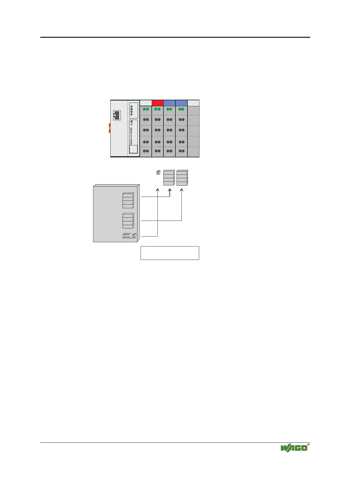
6.3 Example for an Output Process Image
The following example for the output process image comprises 2 digital and 4
analog outputs. It comprises 8 bytes for the analog outputs and 1 byte for the
digital outputs, i.e. 9 bytes in total.
Bit 1
Bit 2
0x0003
0x0002
0x0001
0x0000
AO
DO
AO
LINK
MS
NS
ETHERNET
TxD/RxD
I/O
750-341
Addresses
Process output image
(Byte)
Output modules 750 - 501 550 550
DO: Digital Output
AO: Analog Output
Byte1
Byte2
Byte 3
Byte 4
Byte 2
Byte 1
Byte1
Byte2
Byte 3
Byte 4
Byte 2
Byte 1
Byte1
Byte2
Byte 3
Byte 4
Byte 2
Byte 1
Byte1
Byte2
Byte 3
Byte 4
Byte 2
Byte 1
0x0007
0x0006
0x0005
0x0004
0x0008
Fig. 6-2: Example of an output process image g086058d

Table of Contents

Other manuals for WAGO 750 Series

Questions and Answers:

Question and Answer IconNeed help?

Do you have a question about the WAGO 750 Series and is the answer not in the manual?

WAGO 750 Series Specifications

General IconGeneral
Protection ClassIP20
Bus CouplersPROFIBUS, CANopen, Ethernet
ModulesDigital Input, Digital Output, Analog Input, Analog Output
MountingDIN rail mounting
Voltage Supply24 V DC (typical)
Communication ProtocolDepends on the bus coupler (e.g., PROFIBUS, CANopen, DeviceNet, Ethernet)
Digital Input ChannelsVaries by module (e.g., 8, 16 channels)
Digital Output ChannelsVaries by module (e.g., 8, 16 channels)
Analog Input ChannelsVaries by module (e.g., 2, 4, 8 channels)
Analog Output Channels1, 2, 4 channels (depending on module)
Width12 mm, 24 mm (typical module widths)
Number of ChannelsVaries by module type
Current Consumption per ChannelVaries by module type

Related product manuals