The WAGO-I/O-SYSTEM 750 • 25
Mechanical Setup
WAGO-I/O-SYSTEM 750
Linux Fieldbus Coupler
2.6.9 Wire Connection
All components have CAGE CLAMP® connections.
The WAGO CAGE CLAMP® connection is appropriate for solid, stranded
and finely stranded conductors. Each clamping unit accommodates one
conductor.
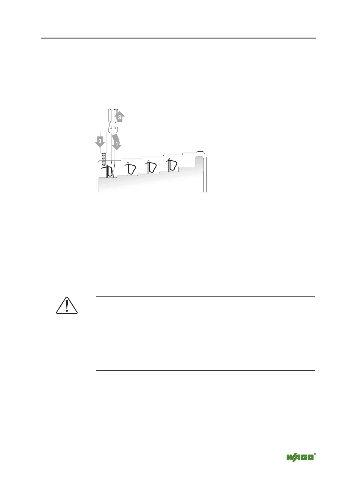
Fig. 2-9: CAGE CLAMP® Connection g0xxx08x
The operating tool is inserted into the opening above the connection. This
opens the CAGE CLAMP
®
. Subsequently the conductor can be inserted into
the opening. After removing the operating tool, the conductor is safely
clamped.
More than one conductor per connection is not permissible. If several
conductors have to be made at one connection point, then they should be made
away from the connection point using WAGO Terminal Blocks. The terminal
blocks may be jumpered together and a single wire brought back to the I/O
module connection point.
Attention
If it is unavoidable to jointly connect 2 conductors, then a ferrule must be
used to join the wires together.
Ferrule:
Length 8 mm
Nominal cross section
max.
1 mm
2
for 2 conductors with 0.5 mm
2
each
WAGO Product 216-103
or products with comparable properties

 Loading...


