EasyManuals Logo

WAGO 750 Series User Manual

WAGO 750 Series
248 pages
To Next Page IconTo Next Page
To Previous Page IconTo Previous Page
Page #39 background imageLoading...
Page #39 background image
The WAGO-I/O-SYSTEM 750 35
Power Supply
WAGO-I/O-SYSTEM 750
Linux Fieldbus Coupler
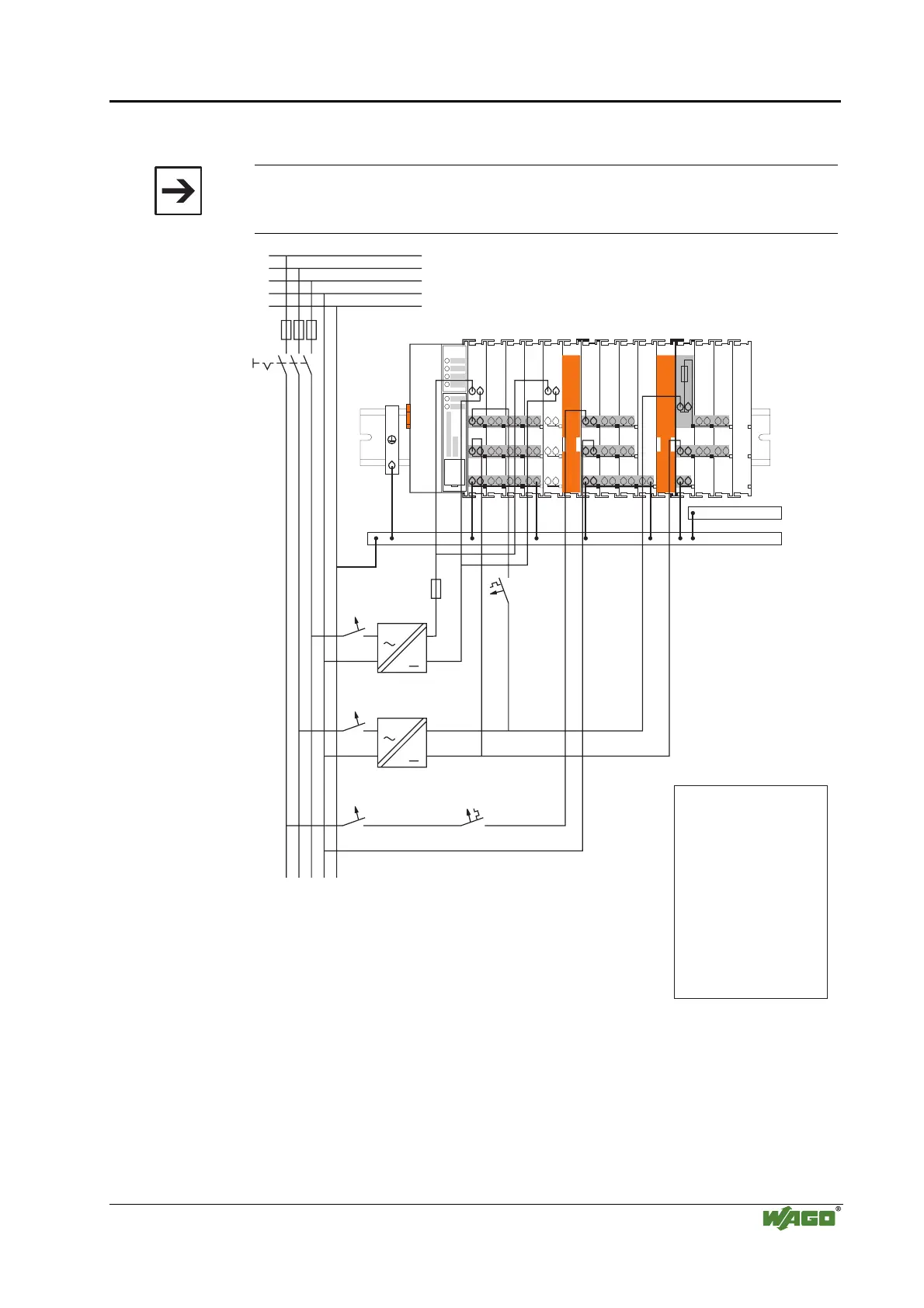
2.7.5 Supply Example
Attention
The system supply and the field supply should be separated in order to ensure
bus operation in the event of a short-circuit on the actuator side.
750-630750-400 750-410 750-401
750-613
750-512 750-512750-616 750-513 750-610 750-552 750-600750-612 750-616
1)
a)
b)
c)
d)
1)
2) 2)
24V
24V
10 A
10 A
L1
L2
L3
N
PE
230V
230V
Main ground bus
Shield (screen) bus
System
Supply
Field
Supply
Field
Supply
1) Separation module
recommended
2) Ring-feeding
recommended
a) Power Supply
on coupler / controller
via external Supply
Module
b) Internal System
Supply Module
c) Supply Module
passive
d)
iagnostics
Supply Module
with fuse carrier/
d
Fig. 2-22: Supply example g0xxx04e

Table of Contents

Other manuals for WAGO 750 Series

Questions and Answers:

Question and Answer IconNeed help?

Do you have a question about the WAGO 750 Series and is the answer not in the manual?

WAGO 750 Series Specifications

General IconGeneral
Protection ClassIP20
Bus CouplersPROFIBUS, CANopen, Ethernet
ModulesDigital Input, Digital Output, Analog Input, Analog Output
MountingDIN rail mounting
Voltage Supply24 V DC (typical)
Communication ProtocolDepends on the bus coupler (e.g., PROFIBUS, CANopen, DeviceNet, Ethernet)
Digital Input ChannelsVaries by module (e.g., 8, 16 channels)
Digital Output ChannelsVaries by module (e.g., 8, 16 channels)
Analog Input ChannelsVaries by module (e.g., 2, 4, 8 channels)
Analog Output Channels1, 2, 4 channels (depending on module)
Width12 mm, 24 mm (typical module widths)
Number of ChannelsVaries by module type
Current Consumption per ChannelVaries by module type

Related product manuals