The WAGO-I/O-SYSTEM 750 • 39
Grounding
WAGO-I/O-SYSTEM 750
Linux Fieldbus Coupler
2.8.3 Grounding Protection
For the field side, the ground wire is connected to the lowest connection
terminals of the power supply module. The ground connection is then
connected to the next module via the Power Jumper Contact (PJC). If the bus
module has the lower power jumper contact, then the ground wire connection
of the field devices can be directly connected to the lower connection
terminals of the bus module.
Attention
Should the ground conductor connection of the power jumper contacts within
the node become disrupted, e. g. due to a 4-channel bus terminal, the ground
connection will need to be re-established.
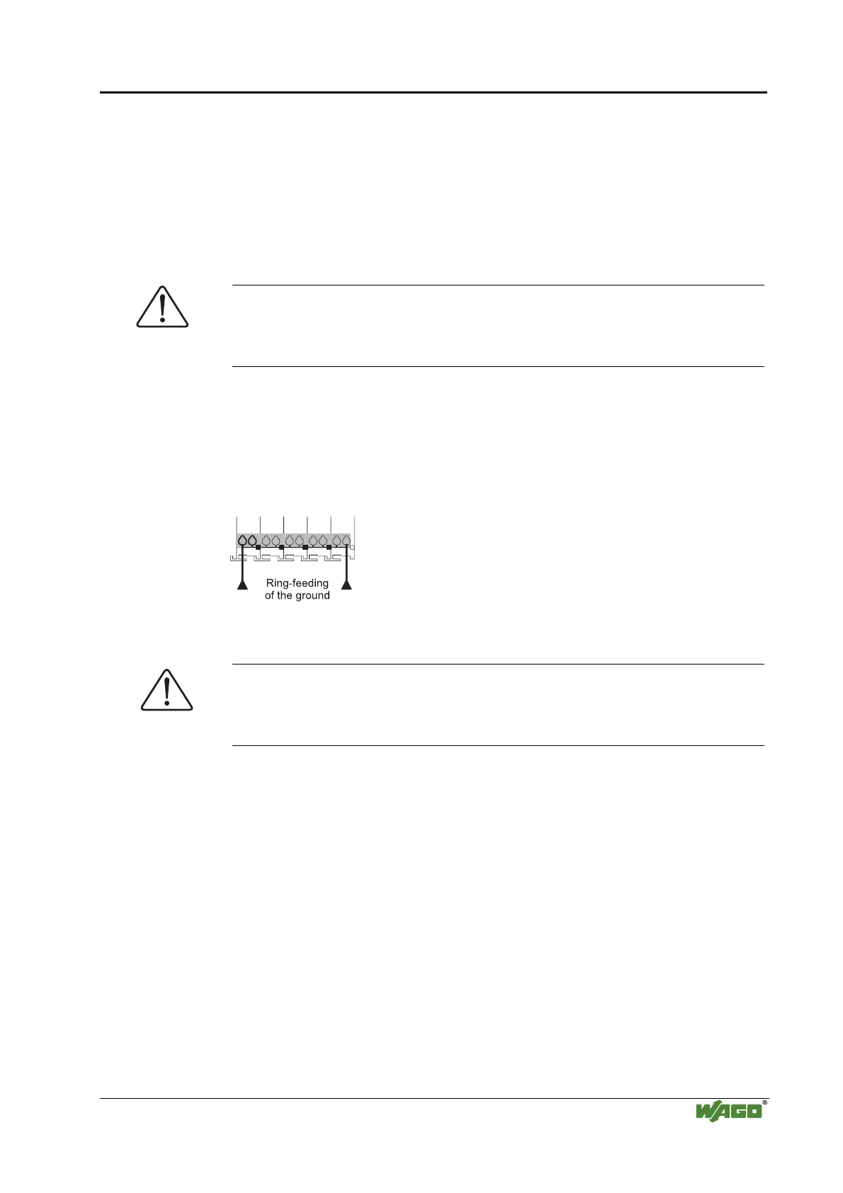
The ring feeding of the grounding potential will increase the system safety.
When one bus module is removed from the group, the grounding connection
will remain intact.
The ring feeding method has the grounding conductor connected to the
beginning and end of each potential group.
Fig. 2-24: Ring-feeding g0xxx07e
Attention
The regulations relating to the place of assembly as well as the national
regulations for maintenance and inspection of the grounding protection must
be observed.

 Loading...


