Linux Fieldbus Coupler 750-860 • 51
Error Indication (IO LED)
WAGO-I/O-SYSTEM 750
Linux Fieldbus Coupler
• Load network driver, IP configuration
• Start init process and any other required process
• Load internal bus driver
During start-up, the "I/O" LED (red) flashes fast. After approximately 20
seconds, the "I/O" LED lights up green and the Linux fieldbus coupler is
operational and the internal bus driver is loaded.
If an error occurs during start-up, it is indicated via the blinking "I/O" LED
(red).
3.10 Error Indication (IO LED)
If errors occur during the operation of the Linux fieldbus coupler, detailed
error messages are indicated via the blink code of the "I/O" LED. The "IO"
LED flashes red.
24V 0V
++
01
02
I/O
C
D
B
A
C
B
A
LINK
STATUS
SERVICE
LINUX
TXD/RXD
USR
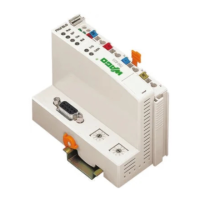
Fig. 3-7: "I/O" LED displaying the blink code g08603x
A blink code consists of three blink sequences with a pause between each
sequence:
• The error display starts with the first blink sequence (approx. 10 Hz).
• After a break, the second blink sequence starts (approx. 1 Hz). The number
of light pulses indicates the Error Code.
• After another break, the third blink sequence starts (approx. 1 Hz). The
number of light pulses indicates the Error Argument.

 Loading...


