30 • The WAGO-I/O-SYSTEM 750
Power Supply
WAGO-I/O-SYSTEM 750
Linux Fieldbus Coupler
2.7.3 Field Supply
2.7.3.1 Connection
Sensors and actuators can be directly connected to the relevant channel of the
bus module in 1/4 conductor connection technology. The bus module supplies
power to the sensors and actuators. The input and output drivers of some bus
modules require the field side supply voltage.
The coupler/controller provides field side power (DC 24V). In this case it is a
passive power supply without protection equipment.
Power supply modules are available for other potentials, e. g. AC 230 V.
Likewise, with the aid of the power supply modules, various potentials can be
set up. The connections are linked in pairs with a power contact.
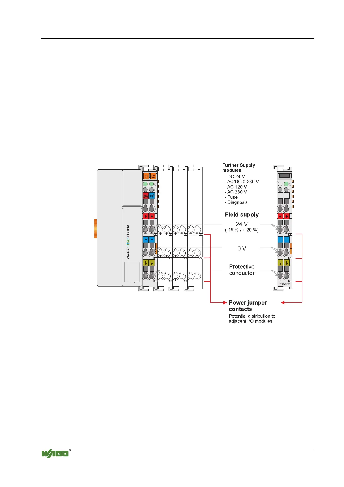
Fig. 2-13: Field Supply (Sensor/Actuator) g0xxx03e
The supply voltage for the field side is automatically passed to the next
module via the power jumper contacts when assembling the bus modules .
The current load of the power contacts must not exceed 10 A on a continual
basis. The current load capacity between two connection terminals is identical
to the load capacity of the connection wires.
By inserting an additional power supply module, the field supply via the
power contacts is disrupted. From there a new power supply occurs which
may also contain a new voltage potential.

 Loading...


