EasyManuals Logo

WAGO 750 Series User Manual

WAGO 750 Series
248 pages
To Next Page IconTo Next Page
To Previous Page IconTo Previous Page
Page #171 background imageLoading...
Page #171 background image
Application Examples • 167
LED Indication Example
WAGO-I/O-SYSTEM 750
Linux Fieldbus Coupler
8.1 LED Indication Example
Program name: leds
Installation directory: /bin/leds
Source code files:
~/uclinux-dist/user/wagoled/leds.h
~/uclinux-dist/user/wagoled/leds.c
Driver/Kernel module: ledman (LED support)
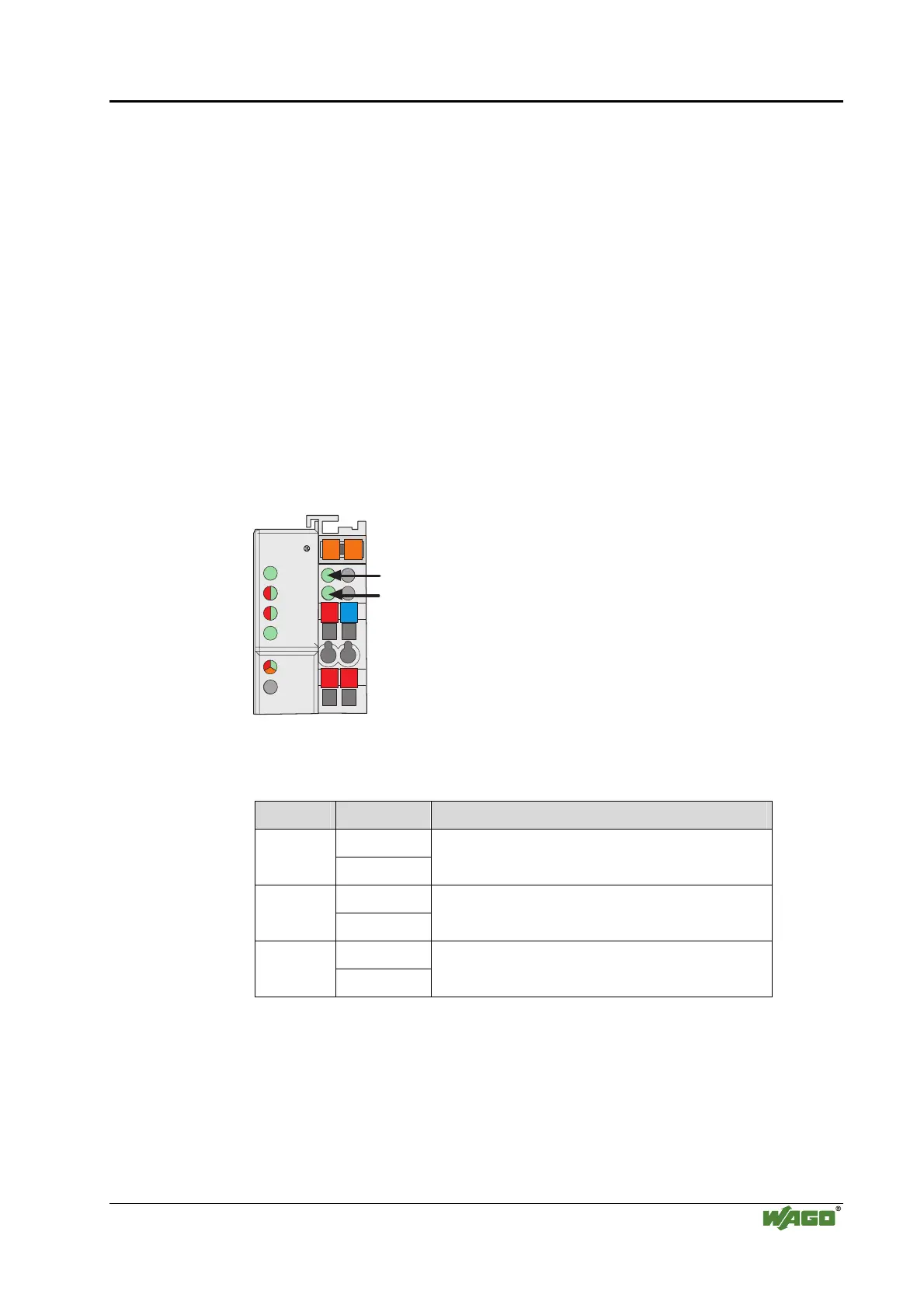
Function description
Using this example program, you can access the freely programmable LEDs:
STATUS, SERVICE and USR.
24V 0V
++
01
02
I/O
C
D
B
A
C
B
A
A
B
LINK
STATUS
SERVICE
LINUX
TXD/RXD
USR
Fig. 8-1: Display elements of the fieldbus coupler g086002x
LED Color Signification
Green/Red STATUS
Off
Function can be defined by the user.
Green/Red SERVICE
Off
Function can be defined by the user.
Green/Red USR
Off
Function can be defined by the user.

Table of Contents

Other manuals for WAGO 750 Series

Questions and Answers:

Question and Answer IconNeed help?

Do you have a question about the WAGO 750 Series and is the answer not in the manual?

WAGO 750 Series Specifications

General IconGeneral
Protection ClassIP20
Bus CouplersPROFIBUS, CANopen, Ethernet
ModulesDigital Input, Digital Output, Analog Input, Analog Output
MountingDIN rail mounting
Voltage Supply24 V DC (typical)
Communication ProtocolDepends on the bus coupler (e.g., PROFIBUS, CANopen, DeviceNet, Ethernet)
Digital Input ChannelsVaries by module (e.g., 8, 16 channels)
Digital Output ChannelsVaries by module (e.g., 8, 16 channels)
Analog Input ChannelsVaries by module (e.g., 2, 4, 8 channels)
Analog Output Channels1, 2, 4 channels (depending on module)
Width12 mm, 24 mm (typical module widths)
Number of ChannelsVaries by module type
Current Consumption per ChannelVaries by module type

Related product manuals