Board Support Package (BSP) • 95
Ethernet Interface Services
WAGO-I/O-SYSTEM 750
Linux Fieldbus Coupler
Dynamic assignments via dhcpcd
If a DHCP server is supposed to be requested after the start of the Linux
kernel, the dhcpcd program can beused. The program is in the /sbin directory
and can hence be started by any user.
The call is dhcpcd &
The DHCP client is started in the background and sends DHCP requests
regularly. With a correct reply, the client automatically configures the Ethernet
interface.
The program is not terminated if a valid response is received from a DHCP
server.
The call can also be a part of the boot script /etc/inittab, of course.
4.6.4 Checking the Network Connection
1. In order to check communication with the Linux fieldbus coupler and the
correct IP address assignment , start the DOS prompt via Start
menu/Programs/Command prompt .
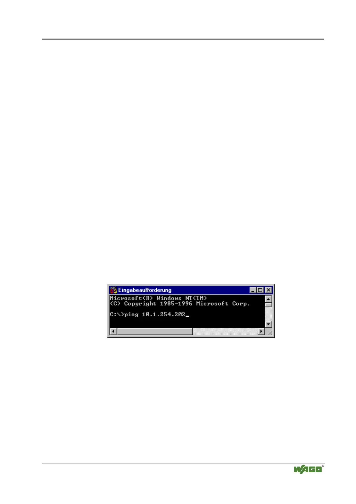
2. Type the command ping using the IP address you assigned and using the
following sytax:
ping [blank] XXX . XXX . XXX . XXX (IP address).
Example: ping 10.1.254.202
Fig. 4-10: Example for a fieldbus node function test p012910d
3. After pressing the return key, your PC gets a response from the Linux
fieldbus coupler which is shown in the DOS promt.
Should the error message: "Request timeout“, appear, please verify your
input and compare it with the IP address you assigned.
After a successful test, you can close the DOS prompt. The node is now ready
to communicate.

 Loading...


