122 • Step-by-Step Guide to your own Linux Application
Debugging of User Space Programs
WAGO-I/O-SYSTEM 750
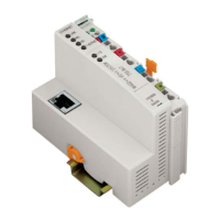
Linux Fieldbus Coupler
To simplify the operation of GDB, a script needs to be generated that creates
defined starting conditions for the debugger. Use the following call to generate
the script:
> emacs gdb.script
Enter the following code into the emacs and save it via CTRL-X, CTRL-S:
If the default IP address of the Linux fieldbus controller has been changed, it
is necessary to also change the IP address that is in the first line of the above-
mentioned script.
In the first line of the script, a remote connection is automatically established
to the GDB server of the Linux fieldbus controller with the IP address
192.168.1.3 using port number 1234. The second line sets a breakpoint to
the main routine and the third line starts the program that runs until the
breakpoint is reached.
5.12.5 Debugging via the GDB Console
In order to enable cross debugging between the PC and the Linux fieldbus
controller, a connection via Ethernet is used. In the procedure described below
the Linux fieldbus controller has the default IP address 192.168.1.3, the Linux
PC has IP address 192.168.1.4. If your settings differ from the settings
indicated above, change the IP addresses so that they match the addresses in
the example.
First, start the GDB server on the Linux fieldbus controller. To do so, change
the directory in which is the program that has been created in the previous
section:
> cd ~/uclinux-dist/user/newProg
Enter the following call into the console:
> gdbserver 192.168.1.4:1234 newProg
target remote 192.168.1.3:1234
b main
continue
 Loading...
