The WAGO-I/O-SYSTEM 750 • 9
System Description
WAGO-I/O-SYSTEM 750
Linux Fieldbus Coupler
2 The WAGO-I/O-SYSTEM 750
2.1 System Description
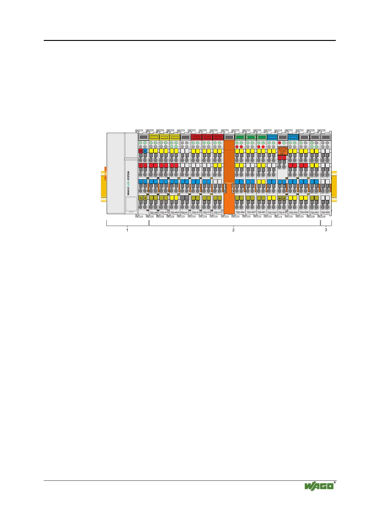
The WAGO-I/O-SYSTEM 750 is a modular, field bus independent I/O
system. It is comprised of a field bus coupler/controller (1) and connected
field bus modules (2) for any type of signal. Together, these make up the field
bus node. The end module (3) completes the node.
Fig. 2-1: Field bus node g0xxx00x
Couplers/controllers for field bus systems such as PROFIBUS, INTERBUS,
ETHERNET TCP/IP, CAN (CANopen, DeviceNet, CAL), MODBUS, LON
and others are available.
The coupler/controller contains the field bus interface, electronics and a power
supply terminal. The field bus interface forms the physical interface to the
relevant field bus. The electronics process the data of the bus modules and
make it available for the field bus communication. The 24 V system supply
and the 24 V field supply are fed in via the integrated power supply terminal.
The field bus coupler communicates via the relevant field bus. The
programmable field bus controller (PFC) enables the implementation of
additional PLC functions. Programming is done with the WAGO-I/O-PRO in
accordance with IEC 61131-3.
Bus modules for diverse digital and analog I/O functions as well as special
functions can be connected to the coupler/controller. The communication
between the coupler/controller and the bus modules is carried out via an
internal bus.
The WAGO-I/O-SYSTEM 750 has a clear port level with LEDs for status
indication, insertable mini WSB markers and pullout group marker carriers.
The 3-wire technology supplemented by a ground wire connection allows for
direct sensor/actuator wiring.

 Loading...


