136 • I/O Modules
WAGO-I/O-SYSTEM 750
Linux Fieldbus Coupler
7 I/O Modules
7.1 Overview
All listed bus modules, in the overview below, are available for modular
applications with the WAGO-I/O-SYSTEM 750.
For detailed information on the I/O modules and the module variations, please
refer to the manuals for the I/O modules.
You will find these manuals on CD ROM „ELECTRONICC Tools and Docs“
(Item No.: 0888-0412) or at http://www.wago.com under Documentation.
More Information
Current information on the modular WAGO-I/O-SYSTEM is available at
http://www.wago.com.
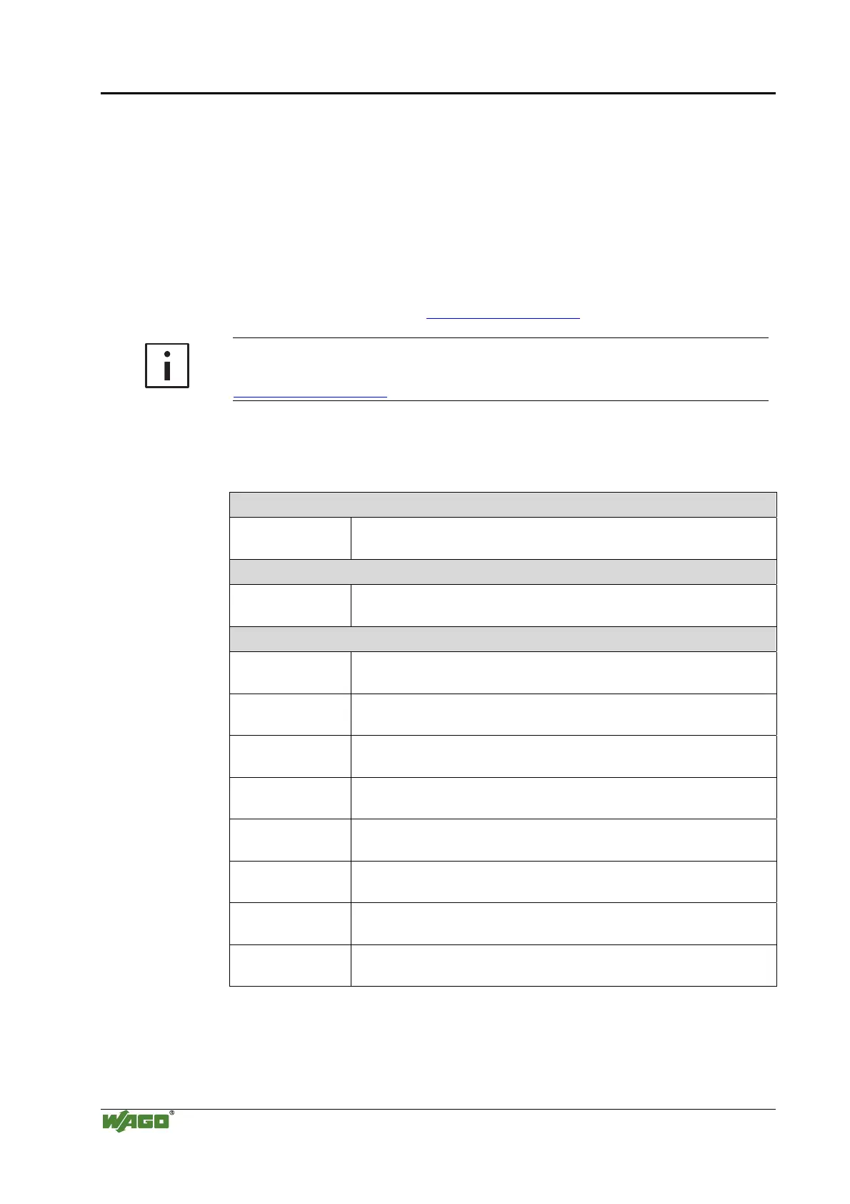
7.1.1 Digital Input Modules
Tab. 7-1: Digital input modules
DI DC 5 V
750-414 4 Channel, DC 5 V, 0.2 ms, 2- to 3-conductor connection,
high-side switching
DI DC 5(12) V
753-434 8 Channel, DC 5(12) V, 0.2 ms, 1-conductor connection,
high-side switching
DI DC 24 V
750-400, 753-400 2 Channel, DC 24 V, 3.0 ms, 2- to 4-conductor connection;
high-side switching
750-401, 753-401 2 Channel, DC 24 V, 0.2 ms, 2- to 4-conductor connection;
high-side switching
750-410, 753-410 2 Channel, DC 24 V, 3.0 ms, 2- to 4-conductor connection;
high-side switching
750-411, 753-411 2 Channel, DC 24 V, 0.2 ms, 2- to 4-conductor connection;
high-side switching
750-418, 753-418 2 Channel, DC 24 V, 3.0 ms, 2- to 3-conductor connection;
high-side switching; diagnostics and confirmation
750-419 2 Channel, DC 24 V, 3.0 ms, 2- to 3-conductor connection;
high-side switching; diagnostics
750-421, 753-421 2 Channel, DC 24 V, 3.0 ms, 2- to 3-conductor connection;
high-side switching; diagnostics
750-402, 753-402 4 Channel, DC 24 V, 3.0 ms, 2- to 3-conductor connection;
high-side switching

 Loading...


