Linux Fieldbus Coupler 750-860 • 49
Hardware Address (MAC ID)
WAGO-I/O-SYSTEM 750
Linux Fieldbus Coupler
3.7 Hardware Address (MAC ID)
Each WAGO Linux fieldbus coupler is provided from the factory with a
unique and internationally unambiguous physical address, also referred to as
MAC ID (Media Access Control Identity). This is located on the rear of the
coupler and on a self-adhesive tear-off label on the coupler side. The address
has a fixed length of 6 bytes (48 bits) and contains the address type, the
manufacturer’s ID, and the serial number.
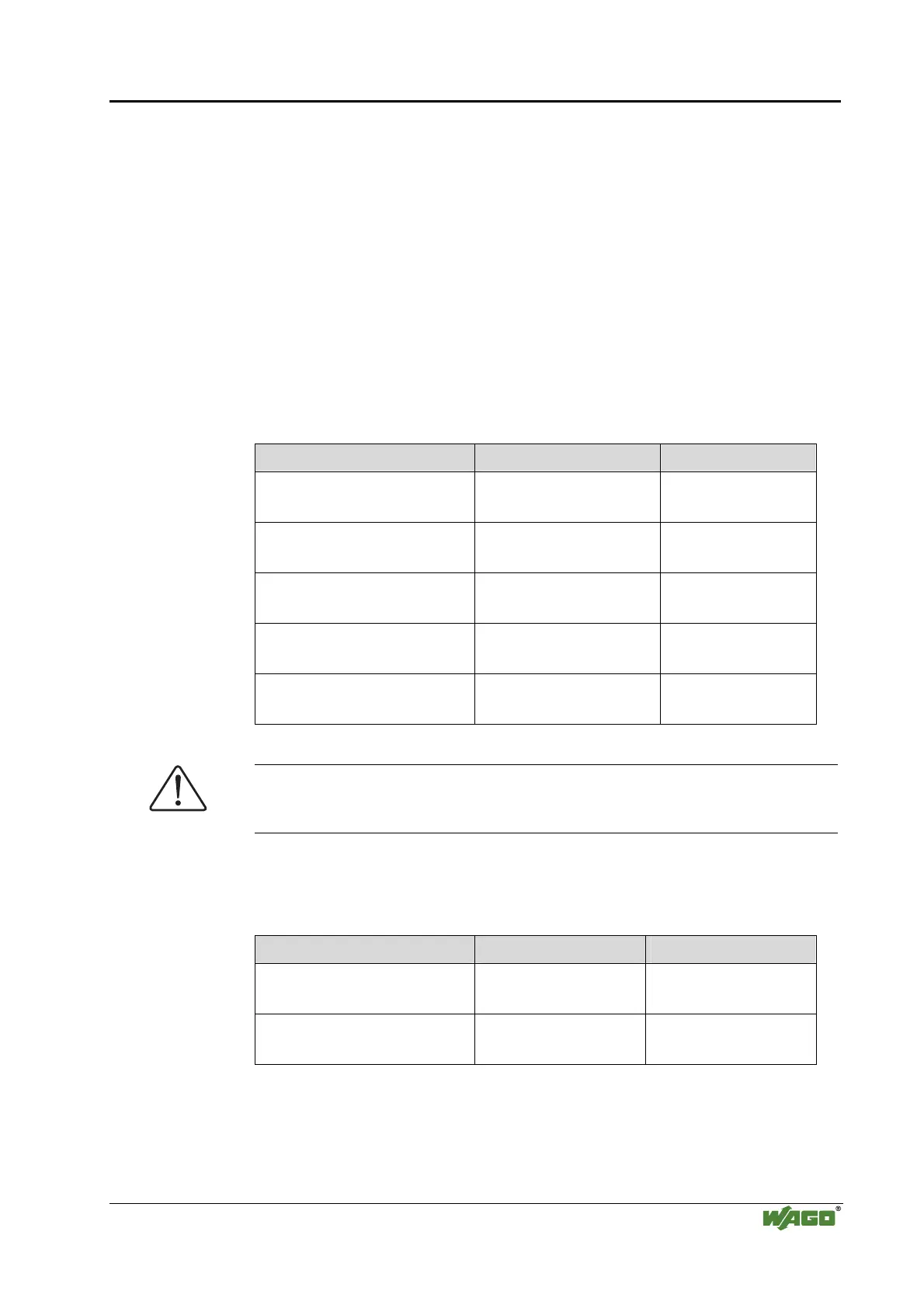
3.8 Memory Map
The memory map in the flash memory looks as follows:
Flash memory address Description Size (approx.)
0x003FFFFF
0x003F0000
Start parameter (U-Boot
environment)
64 kB
0x003EFFFF
0x002D0000
Linux kernel 1.1 MB
0x002CFFFF
0x00040000
File system (JFFS2) 2.6 MB
0x0003FFFF
0x00010000
Boot Loader (U-Boot) 192 kB
0x0000FFFF
0x00000000
BSL and FWL 64 kB
Attention
Do not delete the contents of the BSL/FWL memory addresses.
Otherwise the Linux fieldbus coupler will become inoperative!
Hence, 0x00290000 bytes (approx. 2.69 Mbyte) are available to the file
system. After a successful start of the Linux kernel, the memory map in the
RAM looks as follows:
RAM address Name Size (approx.)
0x00400000
0x00040000
Linux kernel 3.8 MB
0x0003FFFF
0x00000000
Reserved 256 kB
Linux kernel manages the entire free RAM memory.

 Loading...


