144 • I/O Modules
WAGO-I/O-SYSTEM 750
Linux Fieldbus Coupler
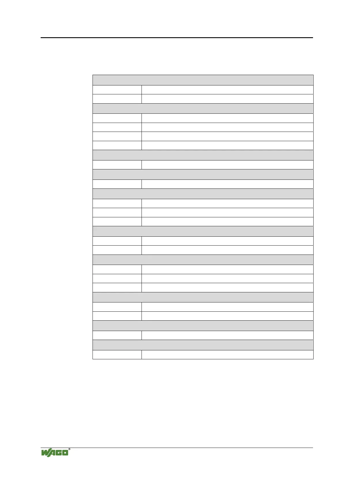
7.1.6 System Modules
Tab. 7-6: System modules
Module Bus Extension
750-627 Module bus extension, end module
750-628 Module bus extension, coupler module
DC 24 V Power Supply Modules
750-602 DC 24 V, passive
750-601 DC 24 V, max. 6.3 A, without diagnostics, with fuse-holder
750-610 DC 24 V, max. 6.3 A, with diagnostics, with fuse-holder
750-625 DC 24 V, EEx i, with fuse-holder
DC 24 V Power Supply Modules with bus power supply
750-613 Bus power supply, 24 V DC
AC 120 V Power Supply Modules
750-615 AC 120 V, max. 6.3 A without diagnostics, with fuse-holder
AC 230 V Power Supply Modules
750-612 AC/DC 230 V without diagnostics, passive
750-609 AC 230 V, max. 6.3 A without diagnostics, with fuse-holder
750-611 AC 230 V, max. 6.3 A with diagnostics, with fuse-holder
Filter Modules
750-624 Filter module, field side power supply
750-626 Filter module, system and field side power supply
Field Side Connection Module
750-603, 753-603 Field side connection module, DC 24 V
750-604, 753-604 Field side connection module, DC 0 V
750-614, 753-614 Field side connection module, AC/DC 0 ... 230 V
Separation Modules
750-616 Separation module
750-621 Separation module with power contacts
Binary Spacer Module
750-622 Binary spacer module
End Module
750-600 End module, to loop the internal bus

 Loading...


