46 • Linux Fieldbus Coupler 750-860
Display Elements
WAGO-I/O-SYSTEM 750
Linux Fieldbus Coupler
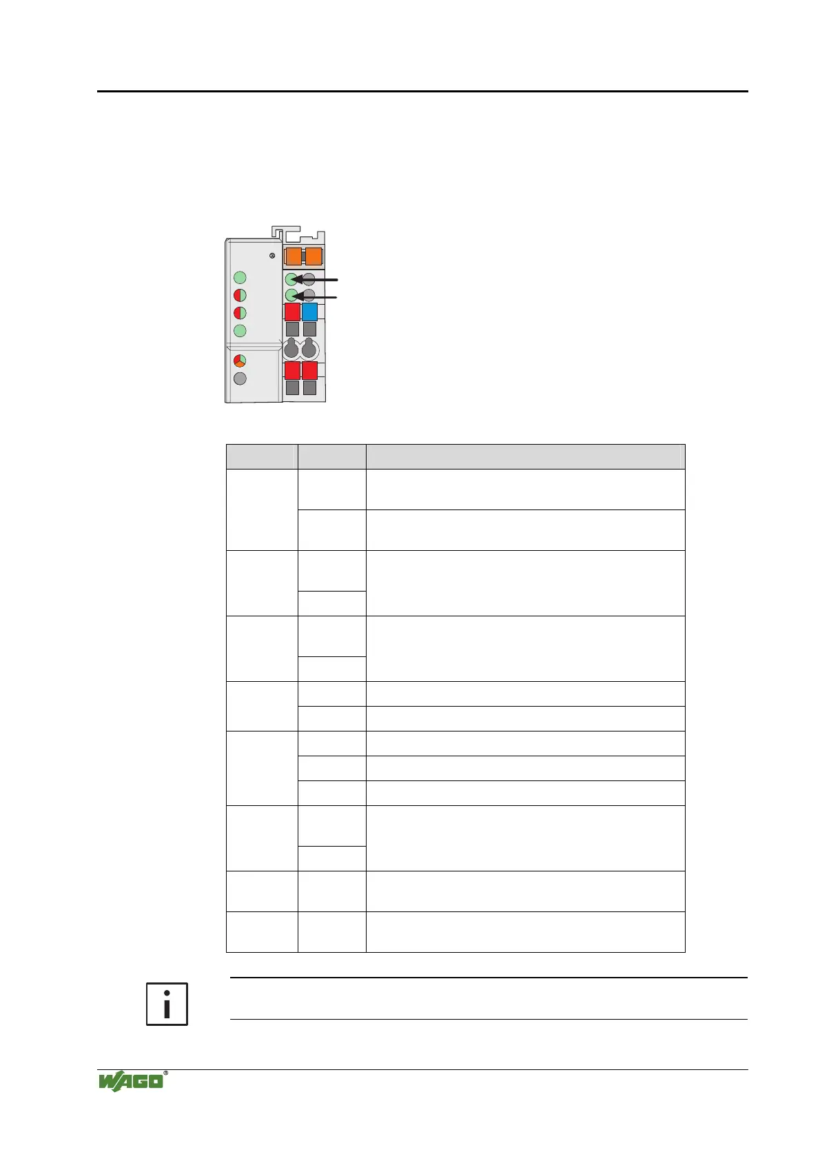
3.4 Display Elements
The operational status of the Linux fieldbus coupler or the fieldbus node is
indicated via LEDs. Optical fibers transmit the LED signals to the upper side
of the enclosure. Some of these signals are colored red and green.
24V 0V
++
01
02
I/O
C
D
B
A
C
B
A
A
B
LINK
STATUS
SERVICE
LINUX
TXD/RXD
USR
Fig. 3-4: Display elements of the fieldbus coupler g086002x
LED Color Meaning
Green Physical connection to the Ethernet network
established.
LINK
Off Fieldbus node has no physical connection to the
Ethernet network.
Green/Re
d
STATUS
Off
Function can be defined by the user.
Green/Re
d
SERVICE
Off
Function can be defined by the user.
Green Data is being exchanged via Ethernet. TxD/RxD
Off No data is being exchanged via Ethernet.
Red Internal bus error or fieldbus coupler error.
Green Linux fieldbus coupler operational, no internal errors.
IO
Off Linux fieldbus coupler not operational.
Green/Re
d
USR
Off
Function can be defined by the user.
A Green Status of operating voltage
24 V supply voltage of the Linux coupler.
B Green Status of operating voltage
Power jumper contacts (field side supply)
More information
The evaluation of the LED signals is described in chapters 3.10 and 8.1.

 Loading...


