192 • Fieldbus Communication
ETHERNET
WAGO-I/O-SYSTEM 750
Linux Fieldbus Coupler
The WAGO ETHERNET TCP/IP fieldbus node does not require any
additional master components other than a PC with a network card. So, the
fieldbus node can be easily connected to local or global networks using the
fieldbus connection. Other networking components such as hubs, switches or
repeaters can also be used. However, to establish the greatest amount of
“determinism” a switch is recommended.
The use of ETHERNET as a fieldbus allows continuous data transmission
between the plant floor and the office. Connection of the ETHERNET TCP/IP
fieldbus node to the Internet even enables industrial processing data for all
types of applications to be called up world-wide. This makes site independent
monitoring, visualization, remote maintenance and control of processes
possible.
10.1.2 Network Architecture – Principles and Regulations
A simple ETHERNET network is designed on the basis of one PC with a
network interface card (NI), one crossover connection cable (if necessary), one
ETHERNET fieldbus node and one 24 V DC power supply for the
coupler/controller voltage source.
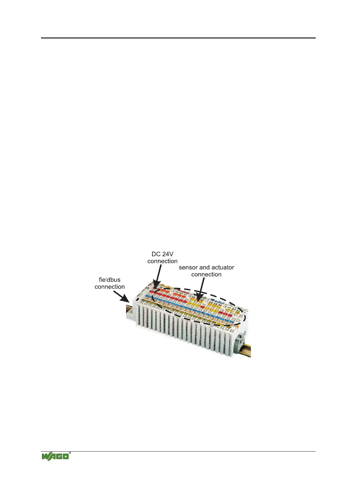
Each fieldbus node consists of a (programmable) fieldbus coupler or
controller and a number of needed I/O modules.
Sensors and actuators are connected to the digital or analog I/O modules on
the field side. These are used for process signal acquisition or signal output to
the process, respectively.
Fig. 10-1. Connection Example and Principle of a Fieldbus Node for a Network Architecture
1Netwerkknotene
Fieldbus communication between master application and (programmable)
fieldbus coupler or controller takes place using the implemented fieldbus
specific application protocol, e. g. MODBUS TCP (UDP), EtherNet/IP,
BACnet, KNXNET/IP, PROFINET, Powerlink, Sercos III or others.

 Loading...


