I/O Modules • 147
Process Data Architecture for MODBUS/TCP
WAGO-I/O-SYSTEM 750
Linux Fieldbus Coupler
750-402, -403, -408, -409, -414, -415, -422, -423, -428, -432, -433,
753-402, -403, -408, -409, -415, -422, -423, -428, -432, -433, -440
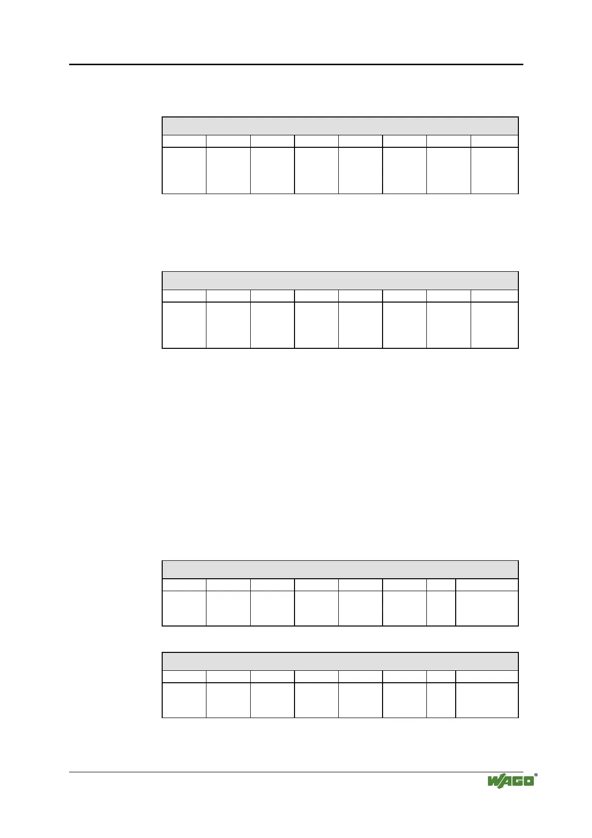
Input Process Image
Bit 7 Bit 6 Bit 5 Bit 4 Bit 3 Bit 2 Bit 1 Bit 0
Data bit
DI 4
Channel
4
Data bit
DI 3
Channel
3
Data bit
DI 2
Channel
2
Data bit
DI 1
Channel
1
8 Channel Digital Input Modules
750-430, -431, -436, -437, 753-430, -431, -434
Input Process Image
Bit 7 Bit 6 Bit 5 Bit 4 Bit 3 Bit 2 Bit 1 Bit 0
Data bit
DI 8
Channel
8
Data bit
DI 7
Channel
7
Data bit
DI 6
Channel
6
Data bit
DI 5
Channel
5
Data bit
DI 4
Channel
4
Data bit
DI 3
Channel
3
Data bit
DI 2
Channel
2
Data bit
DI 1
Channel
1
7.2.2 Digital Output Modules
Digital output modules use one bit of data per channel to control the output
of the corresponding channel. These bits are mapped into the Output
Process Image.
When analog output modules are also present in the node, the digital image
data is always appended after the analog data in the Output Process Image,
grouped into bytes.
1 Channel Digital Output Module with Input Process Data
750-523
Input Process Image
Bit 7 Bit 6 Bit 5 Bit 4 Bit 3 Bit 2 Bit 1 Bit 0
not
used
Status bit
„Manual
Operation“
Output Process Image
Bit 7 Bit 6 Bit 5 Bit 4 Bit 3 Bit 2 Bit 1 Bit 0
not
used
controls
DO 1
Channel 1
2 Channel Digital Output Modules
750-501, -502, -509, -512, -513, -514, -517, -535, (and all variations),
753-501, -502, -509, -512, -513, -514, -517

 Loading...


