148 • I/O Modules
WAGO-I/O-SYSTEM 750
Linux Fieldbus Coupler
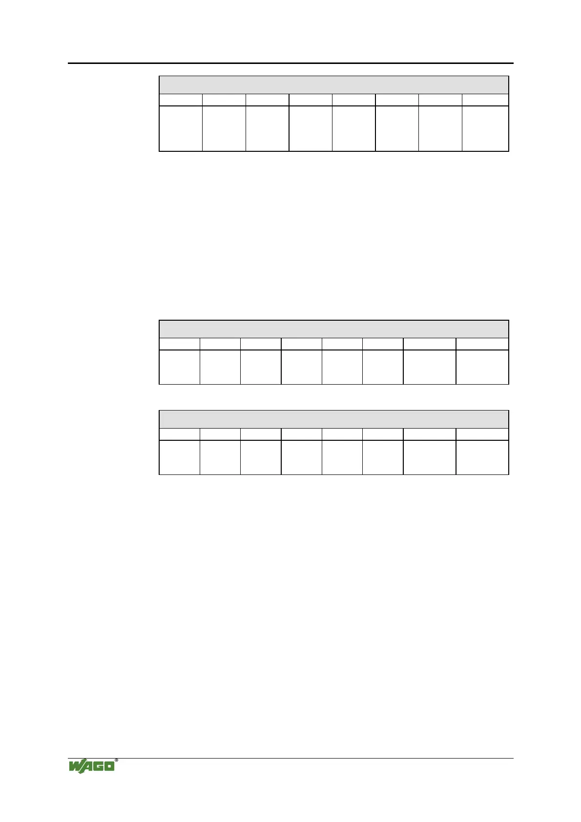
Output Process Image
Bit 7 Bit 6 Bit 5 Bit 4 Bit 3 Bit 2 Bit 1 Bit 0
controls
DO 2
Channel
2
controls
DO 1
Channel
1
2 Channel Digital Input Modules with Diagnostics and Input Process
Data
750-507 (-508), -522, 753-507
The 750-507 (-508), -522 and 753-507 digital output modules have a
diagnostic bit for each output channel. When an output fault condition
occurs (i.e., overload, short circuit, or broken wire), a diagnostic bit is set.
The diagnostic data is mapped into the Input Process Image, while the
output control bits are in the Output Process Image.
Input Process Image
Bit 7 Bit 6 Bit 5 Bit 4 Bit 3 Bit 2 Bit 1 Bit 0
Diagnostic
bit S 2
Channel 2
Diagnostic
bit S 1
Channel 1
Output Process Image
Bit 7 Bit 6 Bit 5 Bit 4 Bit 3 Bit 2 Bit 1 Bit 0
controls
DO 2
Channel 2
controls
DO 1
Channel 1
750-506, 753-506
The 750-506, 753-506 digital output module has 2-bits of diagnostic
information for each output channel. The 2-bit diagnostic information can
then be decoded to determine the exact fault condition of the module (i.e.,
overload, a short circuit, or a broken wire). The 4-bits of diagnostic data
are mapped into the Input Process Image, while the output control bits are
in the Output Process Image.

 Loading...


