124 • Step-by-Step Guide to your own Linux Application
Debugging of User Space Programs
WAGO-I/O-SYSTEM 750
Linux Fieldbus Coupler
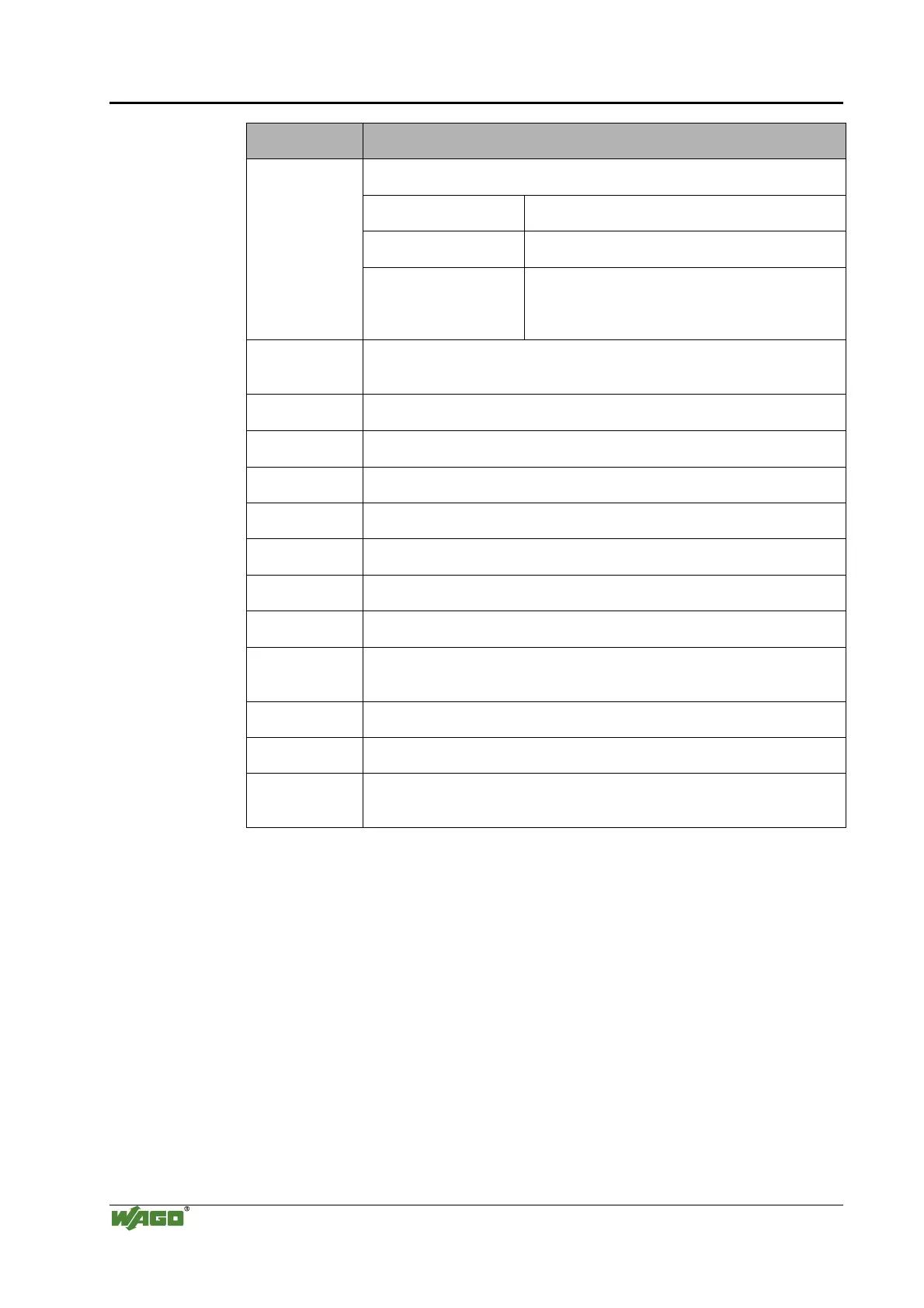
GDB command Description
Sets a breakpoint.
break
newProg.c:20
Sets a breakpoint at line 20 in the main.c file
break main
Sets a breakpoint at the main function start
break
break *0x00dd8080
Sets a breakpoint at the indicated address in the
program code
list
Lists ten code lines around the current position of the program counter.
Another list call will list the next ten lines.
list newProc.c:15 lists ten lines around line 15 in the newProg.c file
print i
Displays the current value of the i variable.
print *pi displays the content of the memory area the pointer pi points to.
display i
Displays the current value of the i variable. The value or the values are
updated after every execution of code (step, next, continue).
undisplay
Undisplays the value that was displayed via the display call before
whatis i
Displays the data type of the i variable.
backtrace
Displays the calling functions and their parameter values from the stack.
where
Displays the content of the stack like backtrace.
set var
i = ?
set var i = 5 sets the i variable to 5.
help.
Displays help texts for the available commands.
help continue, for example, displays a help text for continue,
help set displays the help text for set
quit
Terminates the remote program
exit
Exit the debugger.
run
run call is not possible. The program counter is set to 0x00000000 which,
with the type of CPU used (without MMU), will lead to a restart of the
Linux fieldbus controller.
Debugging via the console is not a very convenient way of doing it, however,
it offers a very good opportunity to control user space programs of the Linux
fieldbus controller via a PC.

 Loading...


