154 • I/O Modules
WAGO-I/O-SYSTEM 750
Linux Fieldbus Coupler
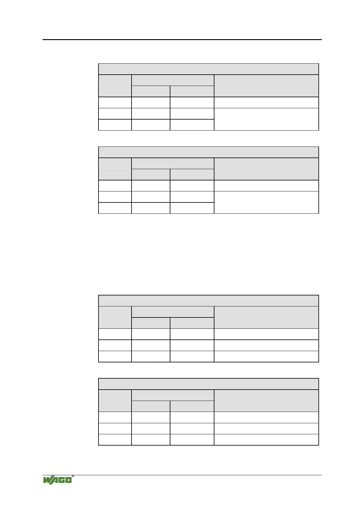
Input Process Image
Byte Destination
Offset
High Byte Low Byte
Remark
0 - S Status byte
1 D1 D0
2 D3 D2
Counter Value
Output Process Image
Byte Destination
Offset
High Byte Low Byte
Remark
0 - C Control byte
1 D1 D0
2 D3 D2
Counter Setting Value
750-404/000-005
The above Counter Modules have a total of 5 bytes of user data in both the
Input and Output Process Image (4 bytes of counter data and 1 byte of
control/status). The two counter values are supplied as 16 bits. The
following tables illustrate the Input and Output Process Image, which has a
total of 3 words mapped into each image. Word alignment is applied.
Input Process Image
Byte Destination
Offset
High Byte Low Byte
Remark
0 - S Status byte
1 D1 D0 Counter Value of Counter 1
2 D3 D2 Counter Value of Counter 2
Output Process Image
Byte Destination
Offset
High Byte Low Byte
Remark
0 - C Control byte
1 D1 D0 Counter Setting Value of Counter 1
2 D3 D2 Counter Setting Value of Counter 2
750-638, 753-638

 Loading...


