164 • I/O Modules
WAGO-I/O-SYSTEM 750
Linux Fieldbus Coupler
AS-interface Master Module
750-655
The length of the process image of the AS-interface master module can be
set to fixed sizes of 12, 20, 24, 32, 40 or 48 bytes.
It consists of a control or status byte, a mailbox with a size of 0, 6, 10, 12
or 18 bytes and the AS-interface process data, which can range from 0 to
32 bytes.
The AS-interface master module has a total of 6 to maximally 24 words
data in both the Input and Output Process Image. Word alignment is
applied.
The first Input and output word, which is assigned to an AS-interface
master module, contains the status / control byte and one empty byte.
Subsequently the mailbox data are mapped, when the mailbox is
permanently superimposed (Mode 1).
In the operating mode with suppressable mailbox (Mode 2), the mailbox
and the cyclical process data are mapped next.
The following words contain the remaining process data.
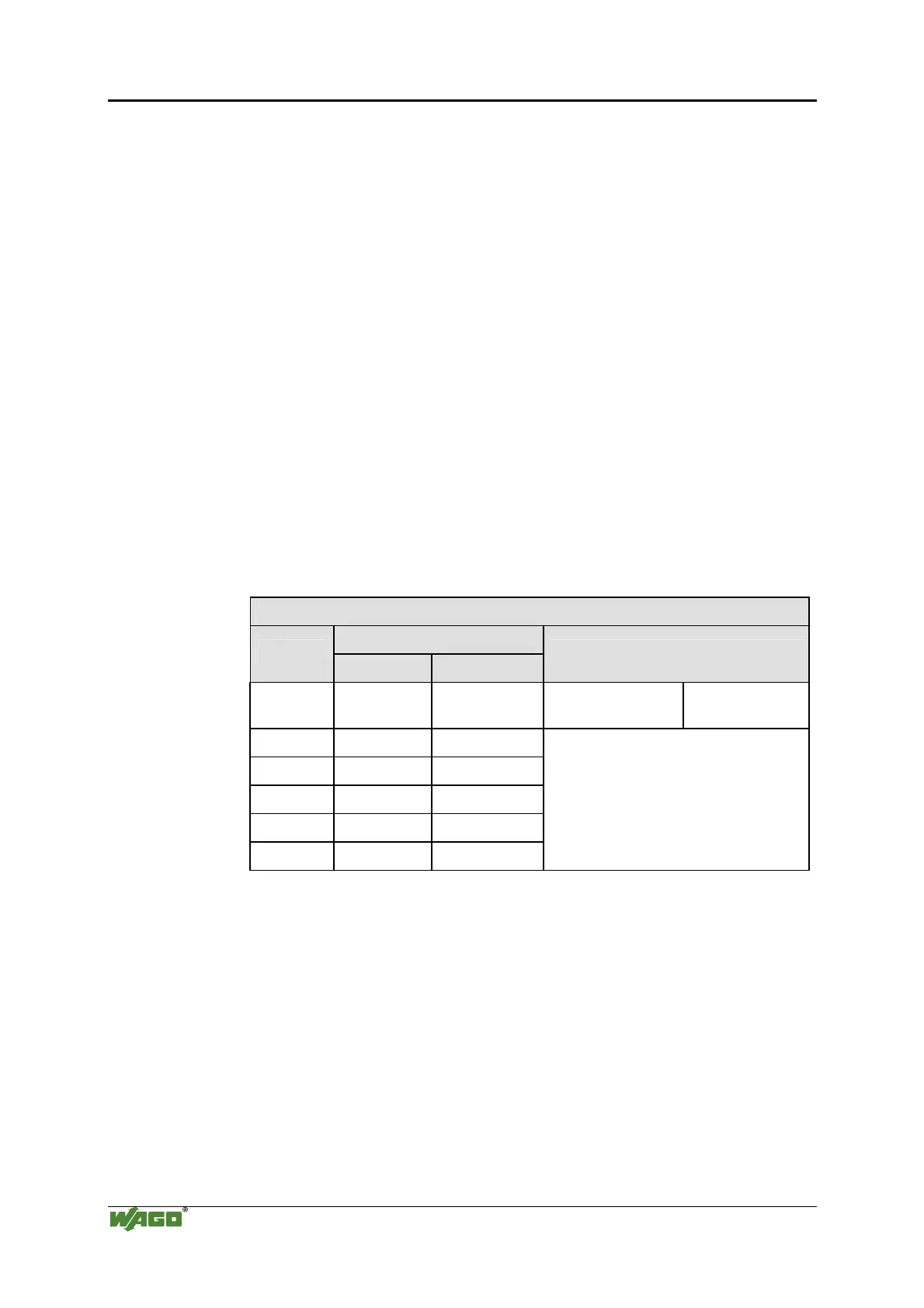
Input and Output Process Image
Byte Destination
Offset
High Byte Low Byte
Remark
0 - C0/S0 not used Control/Status
byte
1 D1 D0
2 D3 D2
3 D5 D4
... ... ...
max. 23 D45 D44
Mailbox (0, 3, 5, 6 or 9 words) /
Process data (0-16 words)

 Loading...


