176 • Application Examples
Example of a Modbus TCP Server
WAGO-I/O-SYSTEM 750
Linux Fieldbus Coupler
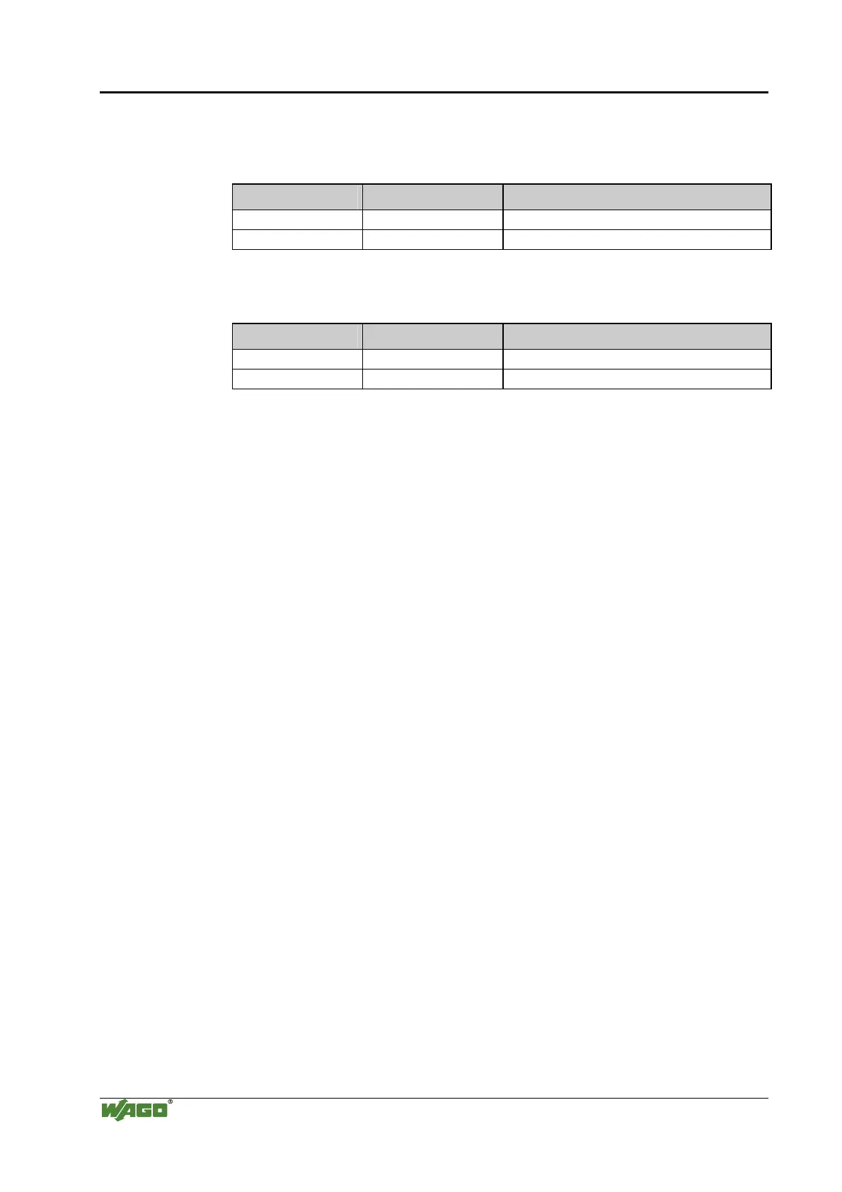
The Modbus addresses are:
Register Read Access:
Start address End address Description
0x0000 0x01FF Inputs of the process image
0x0200 0x03FF Outputs of the process image
Register Write Access:
Start address End address Description
0x0000 0x01FF Outputs of the process image
0x0200 0x03FF Outputs of the process image
The dynamic loadable module "kbus.o" is used for the internal bus support.
In addtition, kbusapi is used which makes it easier to access the internal bus
module. This API (Application Interface) is added to the program during
compilation and linking. The API interfaces are also described in this chapter.
The dynamic loadable module kbus.o serves to access the connected modules
from a user program environment. In order to illustrate the driver interface, the
Linux coupler incorporates the kbusdemo example program. This program can
read or write the state/data of the internal bus via the Linux console.
Source code description
A more detailed description of the source code is not given now. The Modbus
TCP server is only supposed to illustrate a more complex application on the
Linux fieldbus coupler. Furthermore, the program is used to conduct a
functional test of the Linux coupler and is hence installed on every coupler.
The customer can change or extend the source code arbitrarily.

 Loading...


