EasyManuals Logo

WAGO 750 Series User Manual

WAGO 750 Series
248 pages
To Next Page IconTo Next Page
To Previous Page IconTo Previous Page
Page #36 background imageLoading...
Page #36 background image
32 The WAGO-I/O-SYSTEM 750
Power Supply
WAGO-I/O-SYSTEM 750
Linux Fieldbus Coupler
Warning
In the case of power supply modules with fuse holders, only fuses with a
maximum dissipation of 1.6 W (IEC 127) must be used.
For UL approved systems only use UL approved fuses.
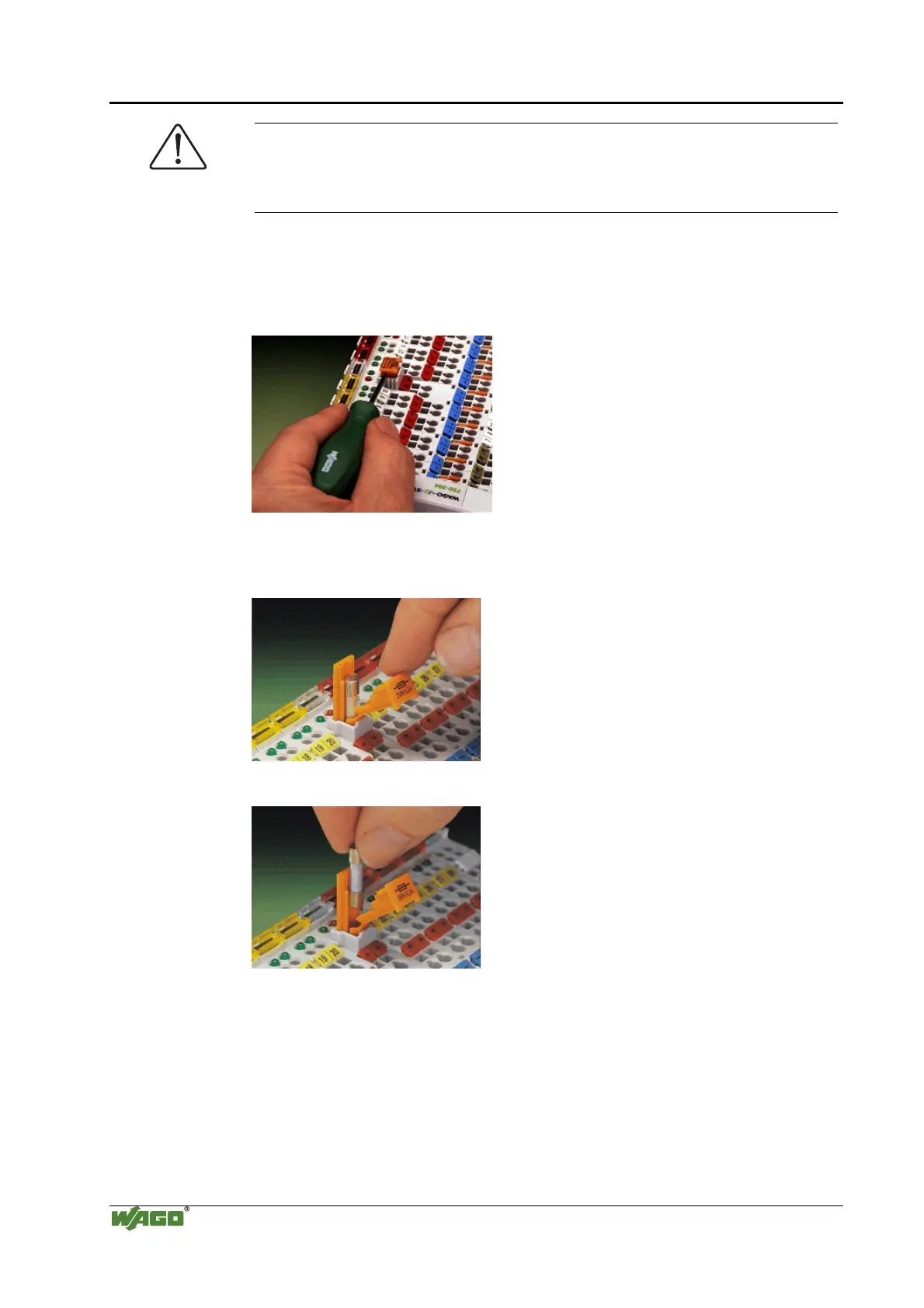
In order to insert or change a fuse, or to switch off the voltage in succeeding
bus modules, the fuse holder may be pulled out. In order to do this, use a
screwdriver for example, to reach into one of the slits (one on both sides) and
pull out the holder.
Fig. 2-15: Removing the fuse carrier p0xxx05x
Lifting the cover to the side opens the fuse carrier.
Fig. 2-16: Opening the fuse carrier p0xxx03x
Fig. 2-17: Change fuse p0xxx04x
After changing the fuse, the fuse carrier is pushed back into its original
position.

Table of Contents

Other manuals for WAGO 750 Series

Questions and Answers:

Question and Answer IconNeed help?

Do you have a question about the WAGO 750 Series and is the answer not in the manual?

WAGO 750 Series Specifications

General IconGeneral
Protection ClassIP20
Bus CouplersPROFIBUS, CANopen, Ethernet
ModulesDigital Input, Digital Output, Analog Input, Analog Output
MountingDIN rail mounting
Voltage Supply24 V DC (typical)
Communication ProtocolDepends on the bus coupler (e.g., PROFIBUS, CANopen, DeviceNet, Ethernet)
Digital Input ChannelsVaries by module (e.g., 8, 16 channels)
Digital Output ChannelsVaries by module (e.g., 8, 16 channels)
Analog Input ChannelsVaries by module (e.g., 2, 4, 8 channels)
Analog Output Channels1, 2, 4 channels (depending on module)
Width12 mm, 24 mm (typical module widths)
Number of ChannelsVaries by module type
Current Consumption per ChannelVaries by module type

Related product manuals