EasyManuals Logo

WAGO 750 Series User Manual

WAGO 750 Series
248 pages
To Next Page IconTo Next Page
To Previous Page IconTo Previous Page
Page #82 background imageLoading...
Page #82 background image
78 Board Support Package (BSP)
Web-Based Management (WBM)
WAGO-I/O-SYSTEM 750
Linux Fieldbus Coupler
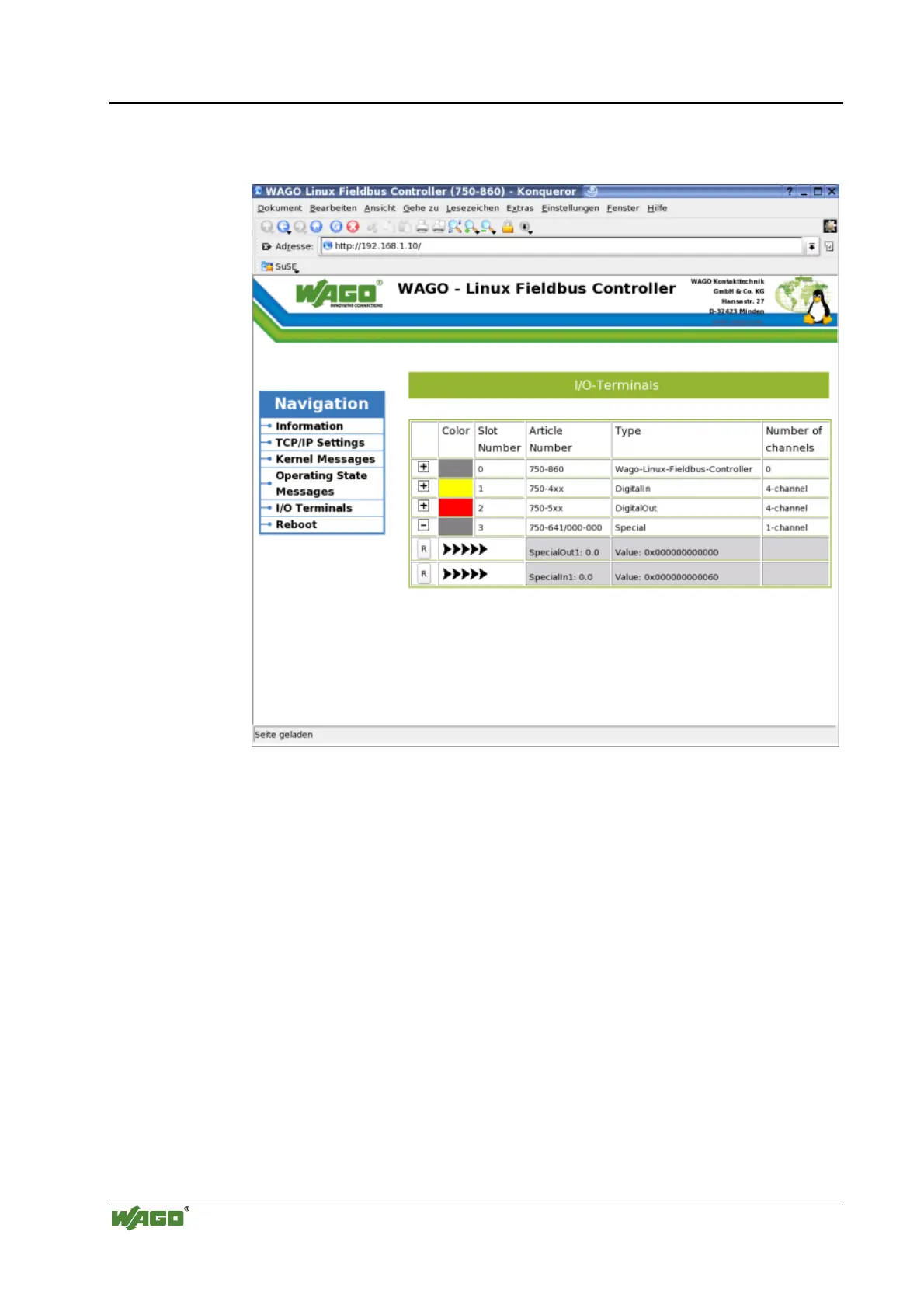
The HTML page Read Config lists all the IO modules that are connected to
the Linux fieldbus coupler and their properties.
Fig. 4-7: Screen view of the IO modules that are connected to theLinux coupler p086003d
I/O Modules
Color
The IO module color indicates the module type. For example, yellow
modules are digital input modules
Slot number
Slot number indicates the position of the IO module behind the Linux
fieldbus coupler
Article number
Item number of the IO module
Type
The type of I/O module is indicated once more (see Color)
Number of channels
Number of channels of the I/O module
Button „R“
Button to open the register tables

Table of Contents

Other manuals for WAGO 750 Series

Questions and Answers:

Question and Answer IconNeed help?

Do you have a question about the WAGO 750 Series and is the answer not in the manual?

WAGO 750 Series Specifications

General IconGeneral
Protection ClassIP20
Bus CouplersPROFIBUS, CANopen, Ethernet
ModulesDigital Input, Digital Output, Analog Input, Analog Output
MountingDIN rail mounting
Voltage Supply24 V DC (typical)
Communication ProtocolDepends on the bus coupler (e.g., PROFIBUS, CANopen, DeviceNet, Ethernet)
Digital Input ChannelsVaries by module (e.g., 8, 16 channels)
Digital Output ChannelsVaries by module (e.g., 8, 16 channels)
Analog Input ChannelsVaries by module (e.g., 2, 4, 8 channels)
Analog Output Channels1, 2, 4 channels (depending on module)
Width12 mm, 24 mm (typical module widths)
Number of ChannelsVaries by module type
Current Consumption per ChannelVaries by module type

Related product manuals