112
wallaceperimetersecurity.comPhone: 866.300.1110
INSTALLER MENU FUNCTIONS
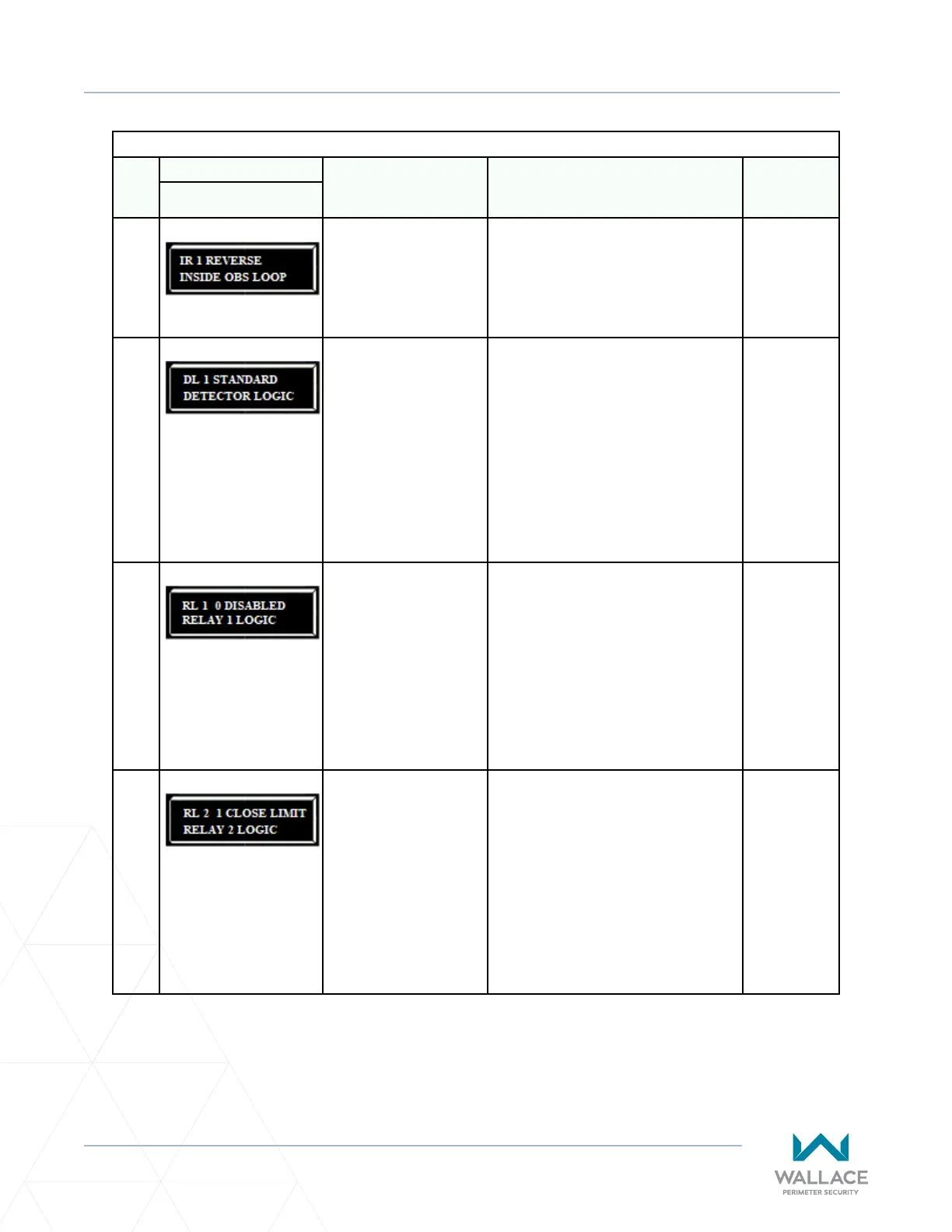
Table 6. SmartDC Controller - Installer Menu Funcons
Ref.
No�
Installer Menu Seng Opons
(Bold = Factory Sengs) Menu Tasks and Explanaons
Associated
DC Controller
Connecons
Display
32
IR 1 REVERSE
INSIDE OBS LOOP
0 = Pause closing only
1 = Enable reversing to
open
The default is for full reversal when the
Inside Obstrucon Loop is triggered. A
seng of 0 causes the gate to only pause
when triggered. Closure begins as soon as
the loop is clear again.
INSIDE OBS
LOOP
COM or HY5A/
HY5B/HY5B
2.0
33
DL 1 STANDARD
DETECTOR LOGIC
1 = Standard
2 = Quick closed
3 = Forced Time out
4 = Full an-tailgate
Congures for faster closure. This
selecon determines whether the close
mer begins to count aer vehicles have
departed the detector loops or whether
the close mer will count down while the
loops are occupied. The gate can only
close when all loop detectors are not
triggered.
Refer to “Vehicle Detector Conguraon
and Quick Close Mode Selecon” on page
126.
HY5A/HY5B/
HY5B 2.0
34
RL 1 0 DISABLED
RELAY 1 LOGIC
0 = Default
1 to 45 available
Congures the funcon of the user 1
output relay, which is a large mechanical
relay. It has the capacity to switch both AC
and DC and can be used for high voltage
and/or high current loads. Connect
devices directly to the top of the relay:
COM plus NO and NC contacts.
Forty-ve oponal logic funcons exist.
See “Seng the User Relay Funcon in
the Installer Menu” on page 141.
User 1 Relay
35
RL 2 1 CLOSE LIMIT
RELAY 2 LOGIC
0 = default
1 to 45 available
Congures the funcon of the user 2
output relay, which is an electronic relay
with the capacity for switching a DC load
only. The User 2 Relay is limited to 48 Volts
DC and 4 amps maximum load. Connect a
device directly to the two spade terminals
at the boom of the control board, next to
the label USER 2.
Forty-ve oponal relay funcons exist.
See “Seng the User Relay Funcon in
the Installer Menu” on page 141.
User 2 Relay