Alpha/Delta (Kinetic Operator) Installation and Maintenance Manual Revision 1 - MAY 2023
113
INSTALLER MENU FUNCTIONS
Table 6. SmartDC Controller - Installer Menu Funcons
Ref.
No�
Installer Menu Seng Opons
(Bold = Factory Sengs) Menu Tasks and Explanaons
Associated
DC Controller
Connecons
Display
36
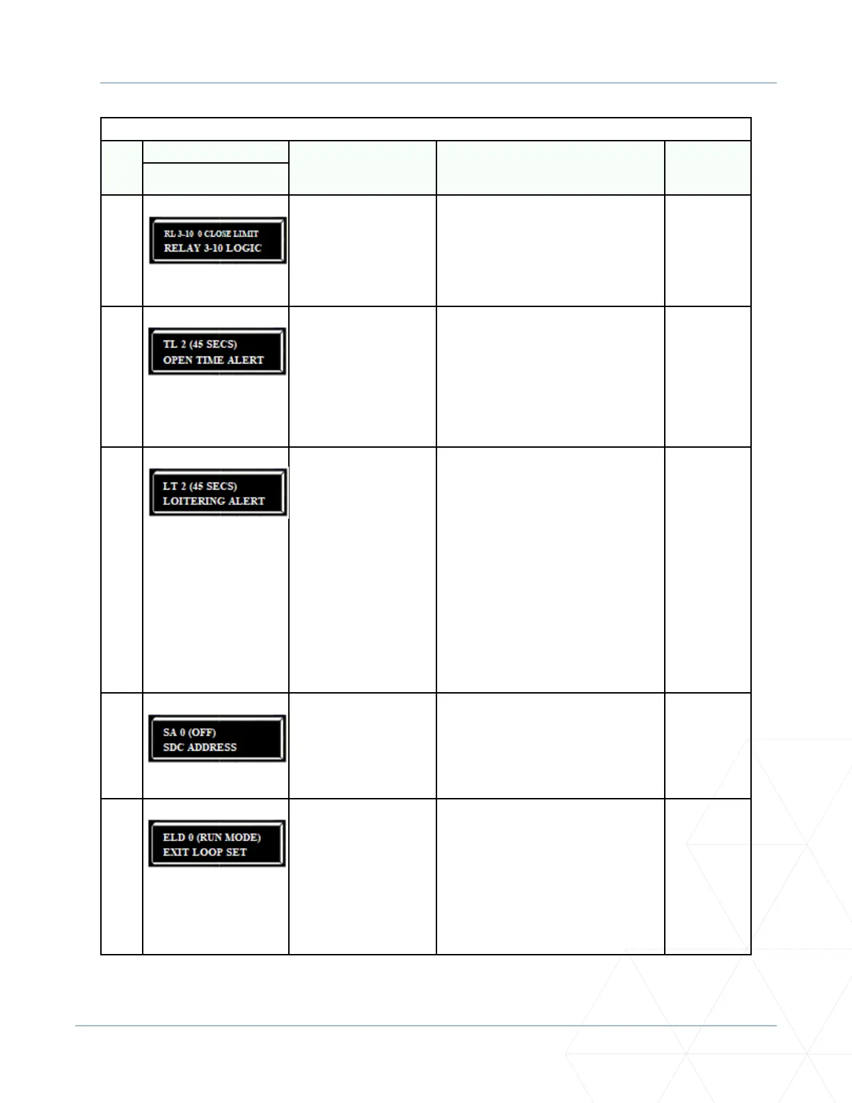
RL 3-10 0 CLOSE LIMIT
RELAY 3-10 LOGIC
0 = Disabled
Up to 45 available
Similar to Relay 1 logic.
Note: The Hy8Relay™ module opon can
be purchased for eight addional NO relay
outputs. Relay #39 set aside for Factory
Use. Use addresses 1-4 when connecng
to HyNet.
User 3 - 10
Relay
37
TL 2 (45 SECS)
OPEN TIME ALERT
0 = 0 seconds
1 = 15 seconds
2 = 45 seconds
3 = 75 seconds
4 = 105 seconds
5 = 135 seconds
Adjusts the me delay before acvang
a user relay. Maximum me seng is
135 seconds. See “Seng the User Relay
Funcon in the Installer Menu” on page
141.
Note: This menu appears only when a
user relay is set to Funcon No. 8.
User relays
38
LT 2 (45 SECS)
LOITERING ALERT
0 = 0 seconds
1 = 15 seconds
2 = 45 seconds
3 = 75 seconds
4 = 105 seconds
5 = 135 seconds
This funcon monitors acvaon of the
Outside Obstrucon Loop when there
is no acvaon of the gate. When the
adjustable period of me is exceeded,
User Relay No. 13 triggers and reports
loitering in the diagnoscs log.
Adjust the me delay before acvang
the user relay. Maximum me seng is
135 seconds. See “Seng the User Relay
Funcon in the Installer Menu” on page
141.
Note: This menu appears only when a
user relay is set to Funcon No. 13.
User relays
39
SA 0 (OFF)
SDC ADDRESS
0 = No network
1 to 99 = Network “drop”
address
Sets the system address for network
communicaon:
0 = no network communicaon.
1-99 sets individual polling addresses. Use
addresses 1-4 when connecng to HyNet.
RS-485
40
ELD 0 (RUN MODE)
EXIT LOOP SET
0 = Run mode
1 = Show frequency
2 = Show call level 0-7
3 = Set Frequency
Controls the HY5A/HY5B/HY5B 2.0
Free
Exit detector. If an HY5B is used, addional
sengs of 4-8 are available:
4 = Show Sensivity
5 = Set Sensivity
6 = Show Inductance
7 = Show Loop Health
8 = Set Presence
HY5A/HY5B/
HY5B 2.0