PROFIBUS DP gateway
Wieland Electric GmbH | BA000970 | 11/2016 (Rev. F)
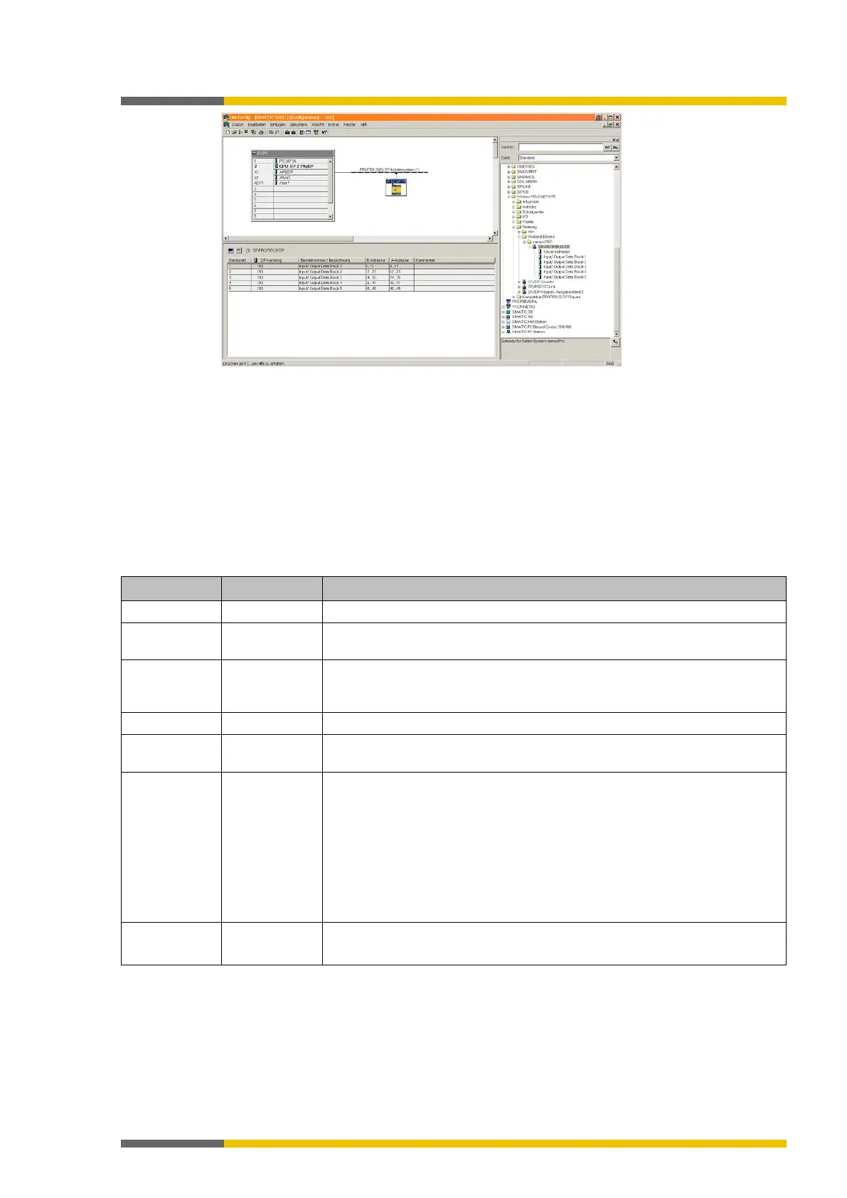
Illustration 44: PROFIBUS-DP gateway in the PROFIBUS HW Config
Diagnosis data of the SP-PROFIBUS-DP module
The SP-PROFIBUS-DP module makes diagnostic data available via PROFIBUS-Standard-DP-V0
diagnosis:
• Standard diagnosis (6 bytes)
• Device-related diagnosis State messages or manufacturer-specific messages
Each module has a unique module ID. The gateway determines the manufacturer-specific di-
agnosis number based on this ID. In this way, module-specific diagnosis texts can be read out
of the GSD. The following table shows the content of the diagnosis messages:
Table 73: Content of the PROFIBUS diagnosis messages
8 See following
Module number
9 0 PROFIBUS slot of the module. The PROFIBUS gateway supports five slots,
which do not, however, represent physical slots. For this reason, all messa-
ges should be assigned to Slot 0 (the gateway itself).
001 = Incoming error , 010 = Outgoing error
10 (Bit 3…7) 00000…11111 Alarm sequence number, increased on each state change of octet 10, bit 0
… 2 (incoming/outgoing error)
11 0 to 14 Position of the module that caused the diagnosis message.
0 = CPU
1 = 1
st
I/O module
…
13 = 1
st
Gateway
14 = 2
nd
Gateway
(Relay output expansions are not counted)
12 to 15 Variable 4 bytes with module-specific diagnosis data.
See below: Table “PROFIBUS error messages”
 Loading...