CANopen gateway
Wieland Electric GmbH | BA000970 | 11/2016 (Rev. F)
CANopen configuration of the gateway - which data are
transferred
910834059
Each CANopen device stores its data in objects listed in the object directory. The service data
objects (SDOs) mainly contain the CANopen configuration data, while the process data are
stored in process data objects (PDOs). Communication objects are used to read and write the-
se SDOs and PDOs and to control the devices. The following sections contain more detailed
descriptions of the various objects.
Predefined Connection Set (PCS)
The Predefined connection set provides a simple CAN identifier structure. The SP-CANopen
gateway makes communication objects available, which can be contacted or transmitted using
this CAN Identifier. The PCS consists of 2 broadcast objects (NMT and SYNC) and a total of 12
peer-to-peer objects. Each of these objects has a clear 11-bit CAN identifier, which consists of
a function code and a device address. The device address for the broadcast objects is 0, while
that for the other objects is within the range of 1 ... 127.
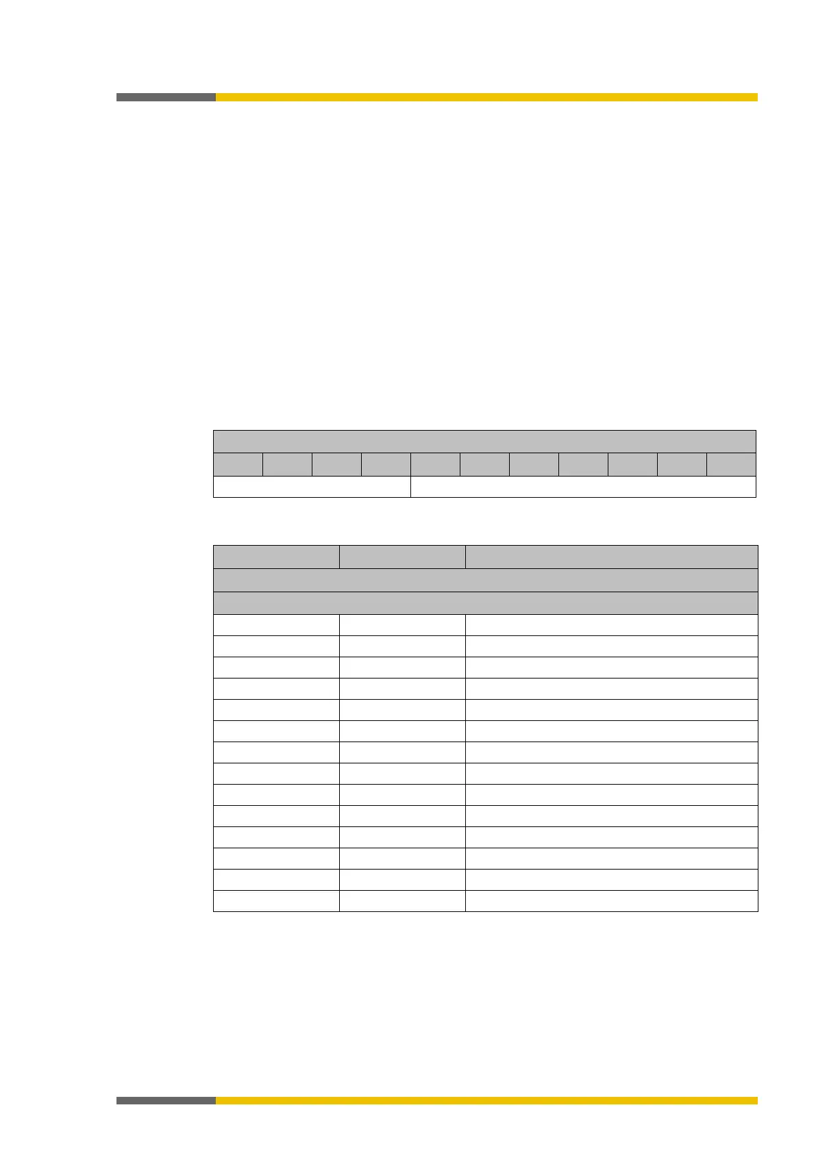
Table 82: Structure of the CAN identifiers
Function code Device address
Table 83: PCS communication objects
Send process data object 1
Receive process data object 1
Send process data object 2
RxPDO2 301h…37Fh Receive process data object 2
Send process data object 3
RxPDO3 401h…47Fh Receive process data object 3
Send process data object 4
Receive process data object 4
Send service data project
RxSDO 601h…67Fh Receive service data object
Each object starts with a CAN identifier, followed by a RTR bit (remote transmission request),
followed by a data length code (DLC), followed by 0 to 8 data bytes. The DLC (4 bits) provides
the number of data bytes.