PROFINET IO-Gateway
Wieland Electric GmbH | BA000970 | 11/2016 (Rev. F)
PROFINET configuration of the gateway - which data are
transferred
1031284363
Cyclical data
The physical I/O modules are not presented in the PROFINET IO hardware catalog as typical
hardware modules in the network. Instead, the data provided by the samosPRO system has
been arranged in various data blocks. Every data block represents a module in the PROFINET
IO hardware catalog. The GSDML supports 13 Slots in which the modules can be placed. This
makes is possible to use each data set one time (see illustration
"Configuration" [ch. 7.4, p.
70]
).
Process data from the samosPRO system for the PLC
The SP-COP2-ENI provides 5 input data blocks (virtual device modules) which contain the pro-
cess image. These can be exclusively placed in each corresponding slot 16 to 20.
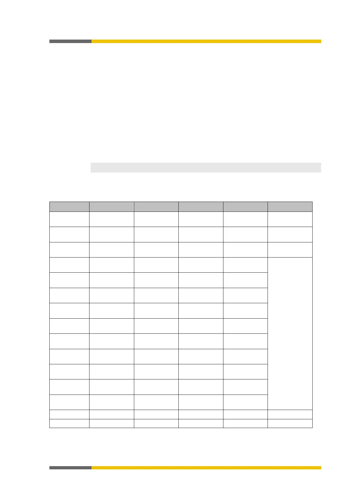
Input data blocks 1 to 4 each contain 12 bytes, while input data block 5 contains 2 bytes.
The content of the input data blocks can be freely selected. The data assignment in samos-
PLAN5+ is pre-configured in accordance with the following:
Table 30: Predefined content of input data block 1 to 5 of the SP-COP2-ENI module
Byte no. per
Input data Input data Input data Input data Input data
Byte 0 Input values SP-
I/O module 1
I/O module 1
Not allocated Not allocated
Byte 1 Input values SP-
I/O module 2
I/O module 2
Not allocated Not allocated
Byte 2 Input values SP-
I/O module 3
I/O module 3
Not allocated Not available
Byte 3 Output values
I/O module 4
I/O module 4
Not allocated
Byte 4 Logic data valu-
I/O module 5
I/O module 5
Not allocated
Byte 5 Logic data valu-
I/O module 6
I/O module 6
Not allocated
Byte 6 Logic data valu-
I/O module 7
I/O module 7
Not allocated
Byte 7 Logic data valu-
I/O module 8
I/O module 8
Not allocated
Byte 8 Logic data valu-
I/O module 9
I/O module 9
Not allocated
Byte 9 Logic data valu-
I/O module 10
I/O module 10
Not allocated
Byte 10 Logic data valu-
es
I/O module 11
input values
I/O module 11
output values
Not allocated
Byte 11 Logic data valu-
I/O module 12
I/O module 12
Not allocated