CANopen gateway
Wieland Electric GmbH | BA000970 | 11/2016 (Rev. F)
PDO communication
910840715
Process data objects (PDOs) are the real-time objects of the CANopen field bus. They are sent
without a protocol overhead, i.e. the receiver sends no confirmation.
The SP-CANopen module provides for transmit process data objects (TxPDOs), which contain
the operating
data to be sent to the network and four receive process
data objects (RxPDOs) for the operating data received from the network.
CANopen objects are addressed with the aid of 11-bit CAN identifiers. As a pre-set, the CAN
identifier derives each object from the object type and the configured CANopen device
address. The CAN identifier of the PDOs can be changed by using SDOs 1400 to 1403 for the
RxPDOs and SDOs 1800 to 1803 for the TxPDOs ("PDO linking").
Each process data object contains 8 bytes.
The content of the process data objects can be freely selected, but has been preconfigured as
follows in samosPLAN5+:
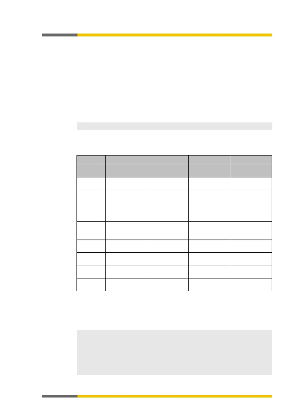
Table 93: Preset for the content of the transmit process data objects (TxPDOs) of the SP-CANopen module
Byte 0
Input values for
Input values for
Input values for
Output values for
Input values for
Input values for
Input values for
Output values for
Input values for
Module 0
Input values for
Module 3
Input values for
Module 11
Output values for
Module 7
Output values for
Module 0
Input values for
Module 4
Input values for
Module 12
Output values for
Module 8
Direct data (Off) 1 Input values for
Output values for
Output values for
Direct data (Off) 2 Input values for
Output values for
Output values for
Direct data (Off) 3 Input values for
Output values for
Output values for
Direct data (Off) 4 Input values for
Output values for
Output values for
Detailed information about the content of the process diagram may be found here:
Configuring the gateway output values (tab 1) [ch. 5.3, p. 44]
You will find further information about how to configure the process diagram here:
•
Configuration of gateways [ch. 5, p. 35]
• Software manual
• The process data can also be written and read with the aid of service data objects SDO
6000 and SDO 6200 (see
SDO communication [ch. 10.9, p. 147]
). Easy access via SDO is
recommended for diagnostic purposes. More rapid PDO communication is to be used for
normal operation.
• After starting up or changing the configuration (either with the aid of the CANopen mas-
ter or with samosPLAN5+), the LED MS of the CANopen gateway flashes red/green until
an initial transmit/receive data exchange has taken place via P
DO or SDO 6000/SDO 6200
in the CANopen network.