Configuration of gateways
Wieland Electric GmbH | BA000970 | 11/2016 (Rev. F)
Function and basic settings
925675019
Routing
910850443
The process diagram transferred to the network from the samosPRO gateways comprises the
operating data (e.g. logic results, state of inputs and outputs) and the diagnostic data (e.g. mo-
dule state, CRCs). These data have been arranged in 4 data sets.
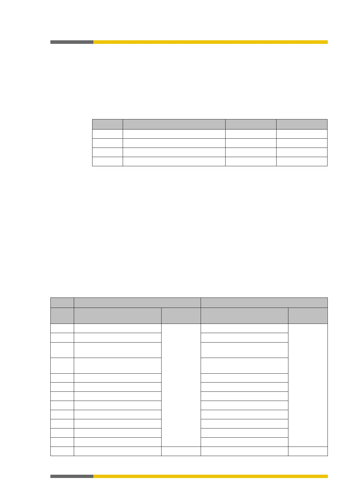
Table 16: Content of data sets 1–4
The operating data in Data Set 1 may consist of up to 50 bytes, irrespective of the network
protocol used. These 50 bytes have been divided into one or several data blocks, depending on
the network protocol. Detailed information about the modularization of the data sent to the
network may be found in the section on the relevant gateway and in the following table:
"Pre-
set configuration for operating data transmitted to the network" [ch. 5.2.2, p. 42]
The content of data set 1 has been preconfigured in the delivery state, but can be freely confi-
gured with a granularity of 1 byte (see
Basic settings for operating data [ch. 5.2.2, p. 42]
and
Configuring the gateway output values (tab 1) [ch. 5.3, p. 44]
).
The diagnostic data in data sets 2-4 depend on the network protocol used and are described in
the chapter on the relevant gateway.
Basic settings for the operating data
910851467
The operating data have been preconfigured in the delivery state. Depending on the gateway
used, these data are divided into several data blocks.
The following table provides an overview of which bytes have been allocated to the preset con-
figuration and how the data at the various gateways are modularized.
Table 17: Preset configuration for operating data transmitted to the network
Input values for Module 0 (I1..I8)
#1
(50 bytes)
Input values for Module 0 (I1..I8)
#1
(12 bytes)
Input values for Module 0 (I9..I16)
Input values for Module 0 (I9..I16)
2 Input values for Module 0
Input values for Module 0
3 Output values for Module 0
Output values for Module 0