Product description
Wieland Electric GmbH | BA000970 | 11/2016 (Rev. F)
Direct gateway output values
910745483
It is possible to write values directly from the logic editor to a gateway. Four bytes have been
reserved for this purpose in the basic settings for data set 1; however, up to the total number
of 50 bytes of data set 1 may be configured as direct gateway output values. You can obtain
additional information at:
Direct gateway output values [ch. 5.3, p. 44]
.
Module state / input and output values
910746507
The samosPRO gateways can transmit the input and output states of all modules connected to
the samosPRO system to the network. Data set 3 contains a non-modifiable configuration. Mo-
reover, data set 1 can be adapted to contain up to 4 bytes of collective state information. Only
the input and output values for data set 1 have been predefined and these can be freely adap-
ted. You will find more detailed information in the section on the relevant gateway, as well as
in the following section:
Configuration of gateways [ch. 5, p. 35]
Module state
The samosPRO gateways can transfer the state of the linked modules to the network. A total
of 4 bytes are available for this purpose.
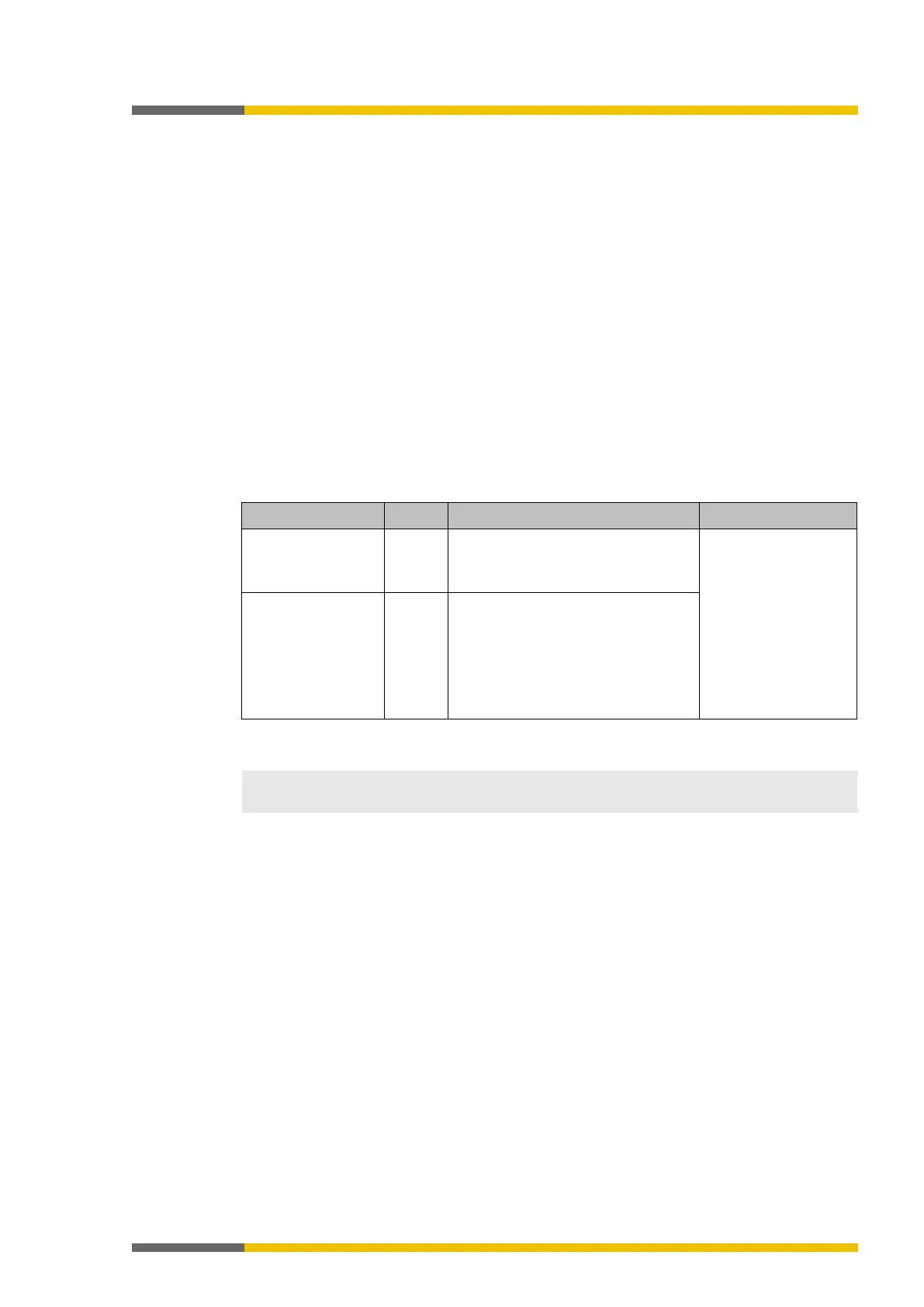
Table 8: Module state
2 bytes One sum bit per module for the state
of the module inputs
Bit 0 = SP-COPx
Bit 1 = 1.
Extension module
Bit 2 = 2.
Expansion module …
Bit 13 = 1.
Gateway Bit 14 = 2.
Gateway Bit 15 =
2 bytes One sum bit per module for the state
of the module outputs
0 = error 1 = no error
You will find information about the meaning of the state bits at: software manual, Status bits
for controller modules (reference)
The input and output states of the SP-SDI and SP-SDIO modules is only available from firm-
ware version V2.00.0.
Input and output values for the modules
•
Input values for I/O modules
1 byte for data set 1 is available for every expansion module. The input values show the
state of the preliminary evaluation of the I/O module. This corresponds to the state of the
element in the controller module logic. The level at the associated terminal cannot be
clearly detected from this, as the data may be set to low, irrespectively of the level at the
input terminal, by means of the cross-connection detection or two-channel evaluation (e.g.
I1-18).
When two-channel input elements have been configured for an I/O module, only the lo-
wer-value bit represents the pre-evaluation state of the corresponding element (e.g. bit 0
for I1 and I2, bit 2 for I3 and I4, bit 4 for I5 and I6, bit 6 for I7 and I8). The higher-value bit
(bit 1, 3, 5 and 7) is used as follows in this case:
0 = error 1 = no error
•
Output values for I/O modules
1 byte for data set 1 is available for every module with outputs. The output values indicate
the state of the control information from the logic of the controller module for the relevant
element of the I/O module. The level of the associated terminals cannot be clearly detected
from this, as the output may be switched off via the cross-connection detection or the
overload connection function.
When two-channel output elements have been configured for an I/O module, only the lo-