Product description
Wieland Electric GmbH | BA000970 | 11/2016 (Rev. F)
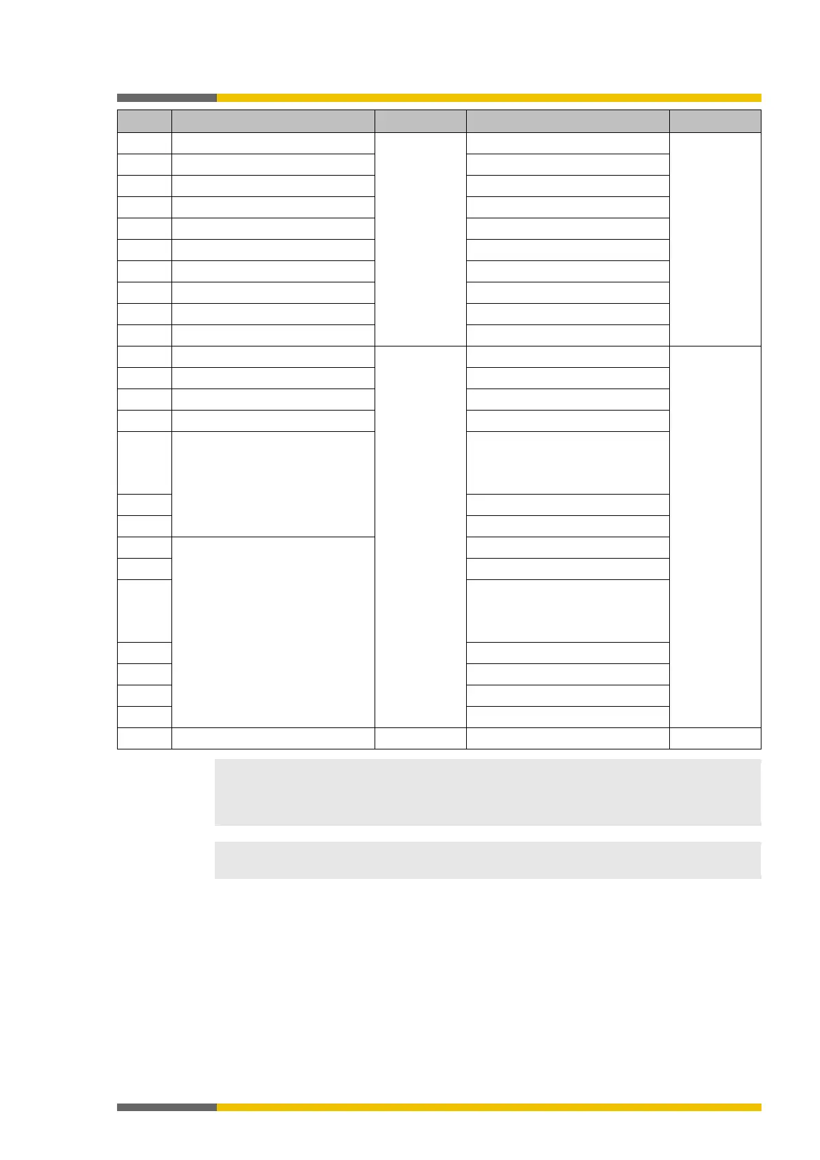
Input values for Module 11
Input values for Module 12
Output values for Module 1
Output values for Module 2
Output values for Module 3
Output values for Module 4
Output values for Module 5
Output values for Module 6
Output values for Module 7
Byte 31 Output values for Module 8 State of Module 5
Output values for Module 9
Not available
Reserved
Byte 33 Output values for Module 10 State of Module 6
Output values for Module 11
Byte 35 Output values for Module 12 State of Module 6
Byte 36
…
Byte 47
Not allocated State of Module 7
…
Not available
Byte 52
…
Byte 55
State of Module 11
…
When two-channel input or output elements have been configured for an I/O module, only
the lowest bit constitutes the in
put or output state (on/off) for the corresponding element. It is
represented by the tag name of the element. The highest bit represents the state of this in-
The input values in data set 1 do not represent the physical state at the input terminals, but
the pre-processed input values that are used for logic processing.