EtherCAT Gateway
Wieland Electric GmbH | BA000970 | 11/2016 (Rev. F)
The samosPRO gateway can transfer the state of the linked modules to the network. A total of
4 bytes are available for this purpose.
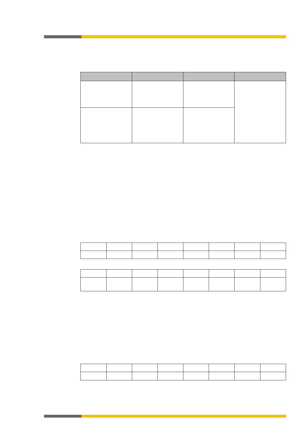
Table 118: Module state
2 bytes One sum bit per mo-
dule for the state of
the module inputs
Bit 0 = SP-COPx
Bit 1 = 1. Module
Bit 2 = 2nd Module
…
Bit 12 = 12th Module
Bit 13 = 1. Gateway
Bit 14 = 2. gateway
2 bytes One sum bit per mo-
dule for the state of
the module outputs
0 = error 1 = no error
You will find information about the meaning of the state bits here in the software manual,
chapter “Status bits for controller modules (reference)"
•
Input values for I/O modules
1 byte for data set 1 is available for every expansion module. The input values show the
state of the preliminary evaluation of the I/O module. This corresponds to the state of the
element in the controller module logic. The level at the associated terminal cannot be
clearly detected from this, as the data may be set to low, irrespectively of the level at the
input terminal, by means of the cross-connection detection or two-channel evaluation (e.g.
I1-18).
When two-channel input elements have been configured for an I/O module, only the lo-
wer-value bit represents the pre-evaluation state of the corresponding element (e.g. bit 0
for I1 and I2, bit 2 for I3 and I4, bit 4 for I5 and I6, bit 6 for I7 and I8). The higher-value bit
(bit 1, 3, 5 and 7) is used as follows in this case:
0 = error 1 = no error
Table 119: Module state (input data status, byte 1)
Bit 7 Bit 6 Bit 5 Bit 4 Bit 3 Bit 2 Bit 1 Bit 0
Table 120: Module state (input data state, byte 2)
Reserved Gateway
Gateway
Module
Module
Module
Module 9 Module 8
•
Output values for I/O modules
1 byte for data set 1 is available for every module with outputs. The output values indicate
the state of the control information from the logic of the controller module for the relevant
element of the I/O module. The level of the associated terminals cannot be clearly detected
from this, as the output may be switched off via the cross-connection detection or the
overload connection function.
When two-channel output elements have been configured for an I/O module, only the lo-
wer-value bit represents the control information (e.g. bit 0 for Q1 and Q2, bit 2 for Q3 and
Q4, bit 4 for Q5 and Q6, bit 6 for Q7 and Q8). The higher-value bit (bit 1, 3, 5 and 7) is not
used as follows in this case (low):
Table 121: Module state (output data status, byte 1)