Product description
Wieland Electric GmbH | BA000970 | 11/2016 (Rev. F)
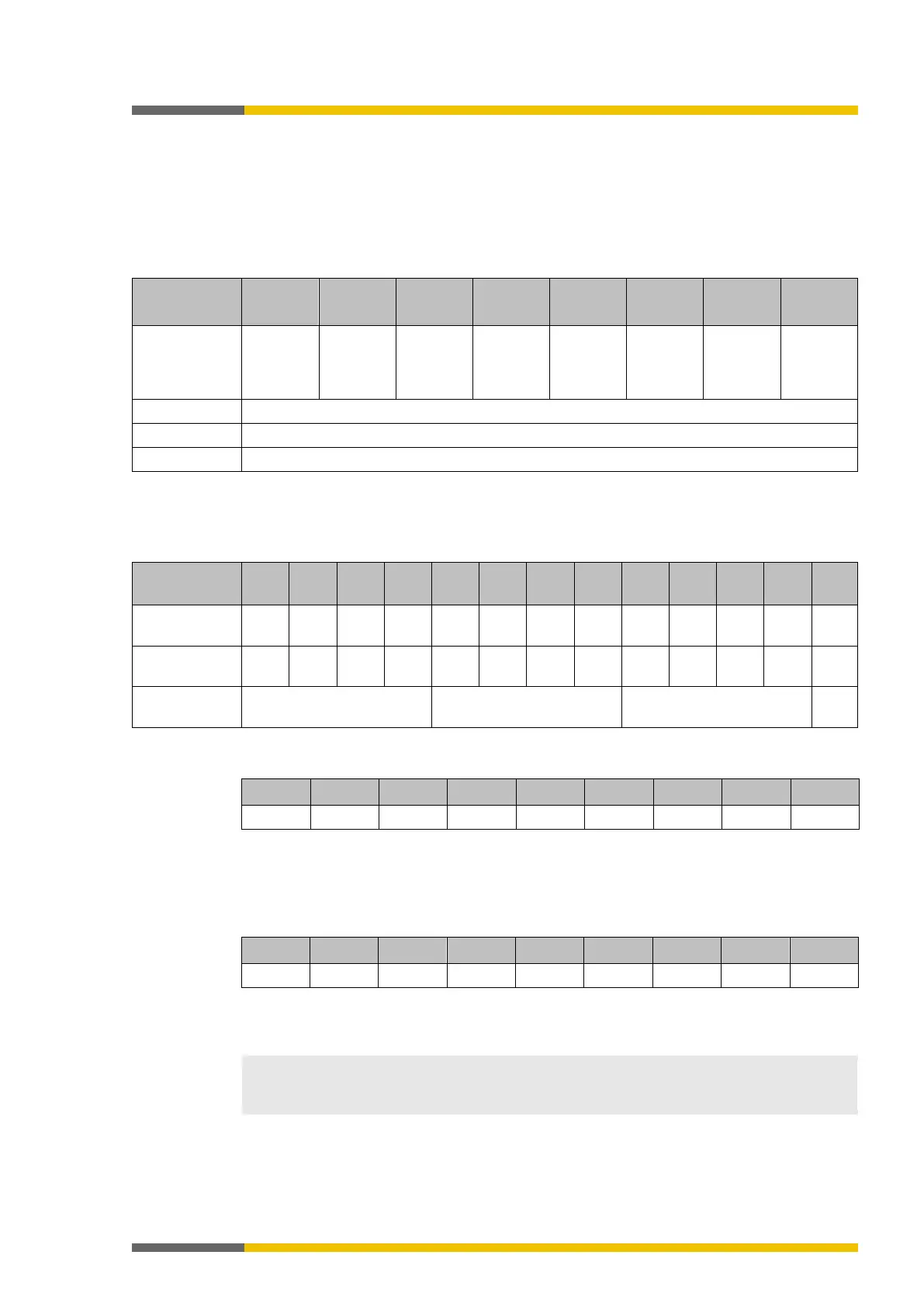
Module state bit of the gateways
The module state bits have the following meaning if not otherwise indicated; normally only the
first byte of the total state is transmitted:
0 = error
1 = no error
Table 12: Meaning of gateway module state bits
Reserved Module
state
output
Module
state
input data
Configura-
tion state
Not used
(error
history
Reserved Internal
module
state
Not used
("execut-
ing state")
Example
Module 2 (SP-SDIO) has a short-circuit after high (24 V) at output 3. The following module sta-
te is transmitted to the network (only the first 20 of 60 bytes are shown):
3
2 1 1
0
3 0 2 1 1 2 0 3 3 0 2
1 2 0 3 …
FF FF FF FF FF FF FF FF
FF FF
…
CPU state State of module 1 (SP-
SP-
…
The first relevant byte for the module 2 error described above is module state byte 0 for modu-
le 2. This is byte 11 with the hexadecimal value FB (1111 1011):
This corresponds to the error message "Summary of bits 0.5 ibs 0.7 (external error)", byte 0, bit
2 in the following table:
"Meaning of module state bits of the secure I/O modules" [ch. 3.3.5, p.
25]
The second relevant byte is the module state byte 3 for module 2. This is byte 08 with the he-
xadecimal value EF (1110 1111):
This corresponds to the error message "Short circuit monitoring of output 3, short circuit after
high", byte 3, bit 4 in the following table:
"Meaning of module state bits of the secure I/O mo-
dules" [ch. 3.3.5, p. 25]
• Reserved (for future use) = static 1 (no state change)
• Not used (can be 0 or 1 ), both values occur.
• If there is no module, all values - including the reserved values - are set to logical 1.