Configuration of gateways
Wieland Electric GmbH | BA000970 | 11/2016 (Rev. F)
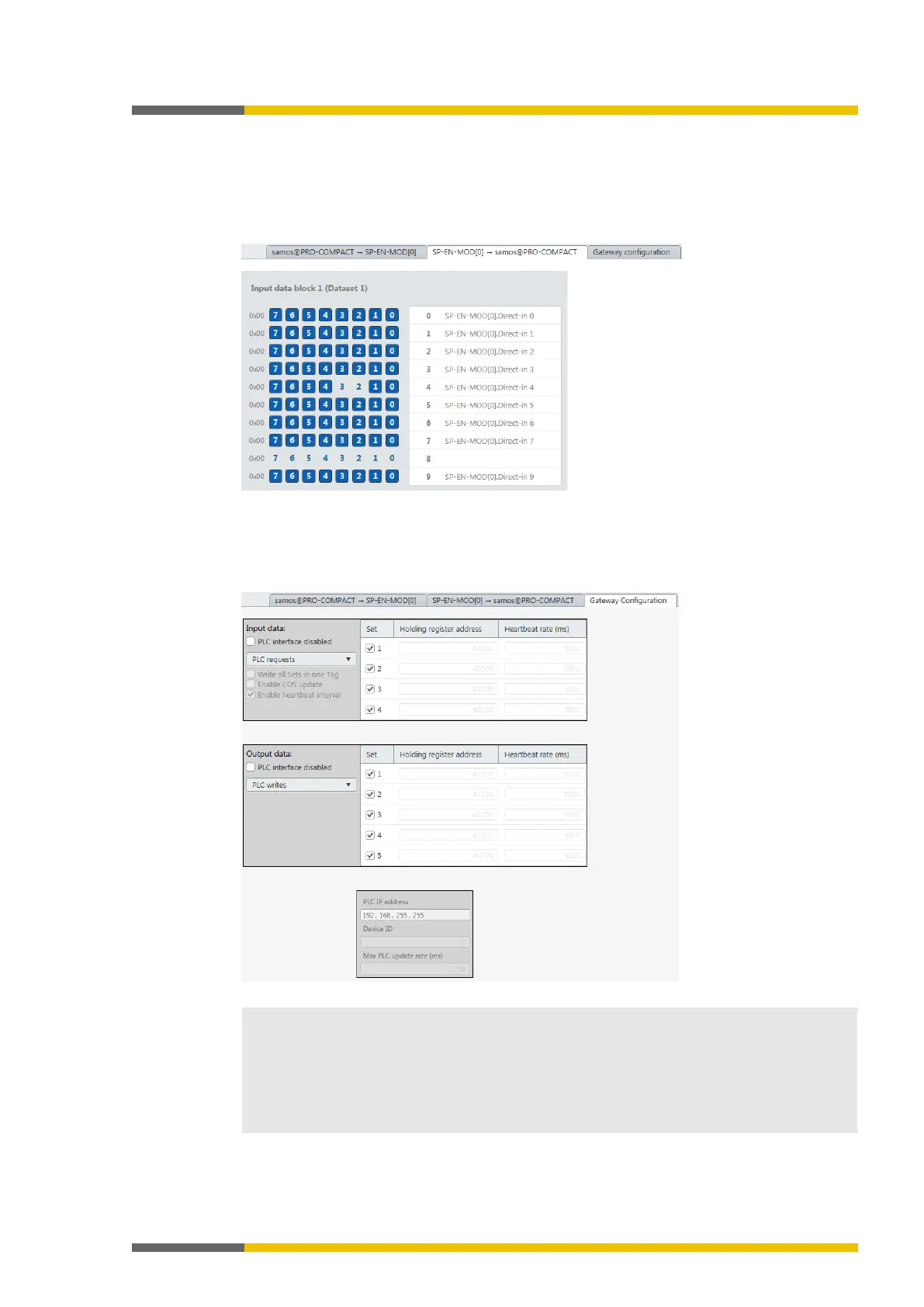
Tab 2: Routing table with input values (data bytes)
Transmission direction: Network/field bus -> samosPLAN5+
When you are working with several gateways: This shows the mapping (the bits used are high-
lighted in blue), while the input data for the various gateways are shown in online mode (byte
display 0x00 at the beginning of the relevant line).
Illustration 5: Routing table with input values
Tab 3: "Gateway configuration"
Tab 3 only appears when you have activated the gateway function on the SP-COP2-ENI modu-
le.
Illustration 6: "Gateway configuration" tab
Allocation of input and output data
The output and input data listed here refer directly to the data blocks in tab 1 and tab 2.
•
group
:
Only
can be configured. This refers directly to
in tab 1.
•
group
:
to
refer directly to
to
in tab