EtherNet/IP gateway
Wieland Electric GmbH | BA000970 | 11/2016 (Rev. F)
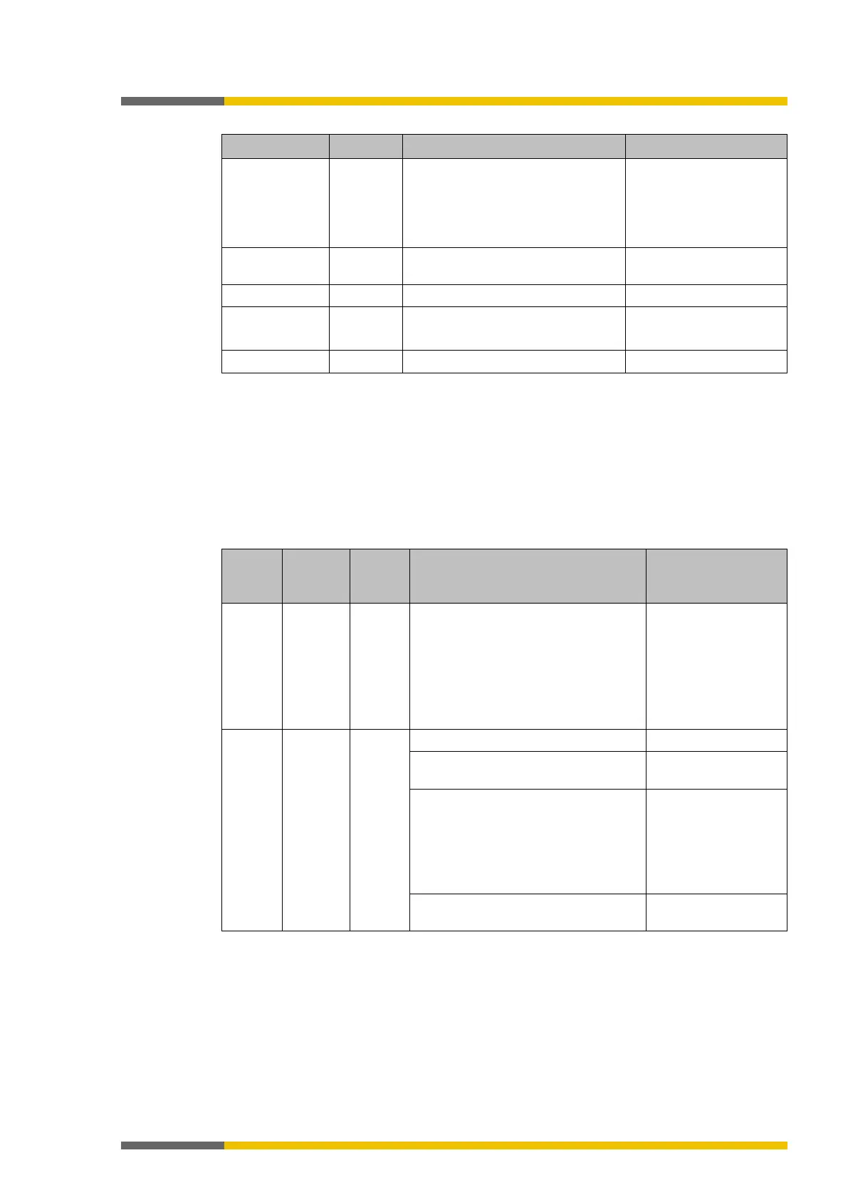
Table 52: Feedback to the SP-COP2-ENI module for reading the data structure of the PLC-5 input
Type ID BYTE Data type and size Bit 0 to 3: 10 = Size spe-
cification in the next but
one byte
Bit 4 to 7: 9 = Type in the
Type ID BYTE Data type 9 = Field of the same
Number of following bytes
Type ID BYTE Data type and size Bit 0 to 3: 2 = UINT
2⋅n = Number of data bytes
The command data of all assembly instances can be recorded using “Read input”.
In contrast to native addressing of EtherNet/IP assembly instances, the PLC-5 system address
contains an element offset which can be used.
The SP-COP2-ENI module supports fields (arrays) of UINT as PCCC data types. Due to the odd
size of the assembly instance 57, the firmware contained in the SP-COP2-ENI module assigns
an additional byte, to provide an even number of bytes.
The address scheme supported by the SP-COP2-ENI module for Read PLC-5 input is shown in
the following table:
Table 53: Read address structure of PLC-5 input
$N57:x UINT[n] n Input assembly of the device profile
Discrete I/O device ,
x = 0 to 33, n = 34 - x
Element 1 to 33:
0 to 65535
Element 34 Bit 0 to 7
(LSB): 0x00, 0x40,
0x80, 0xc0
Element 34 Bit 8 to 15
(MSB): 0
$N167:x UINT[n] n
Logic input bits
(n = 1-x to 25-x, x = 0 to 24)
0 to 65535
System state and system mode
(n = 26-x, x = 0 to 25)
Bit 0 to 7 (LSB):
System mode (1, 2, 3,
4, 5, 7, 21)
Bit 8 to 15 (MSB):
System state (0x00,
State bytes of the controller module
(n = 27-x to 56-x, x = 26 to 55)
0 to 65535
Example: “$N57:10” and “Total Transaction = 24” address elements 11 to 34 correspond to
bytes 20 to 66 of assembly instance 57.
Note: Byte 67, which is not specified in assembly instance 57, is also transferred.
Note: The position of the word data with system state and system mode are dependent on the
requested amount of data “x”.
1127364491