Operation0070−1/A1
Winterthur Gas & Diesel Ltd.
4/ 5
3. Controllable Pitch Propeller (CPP)
3.1 Load Ranges
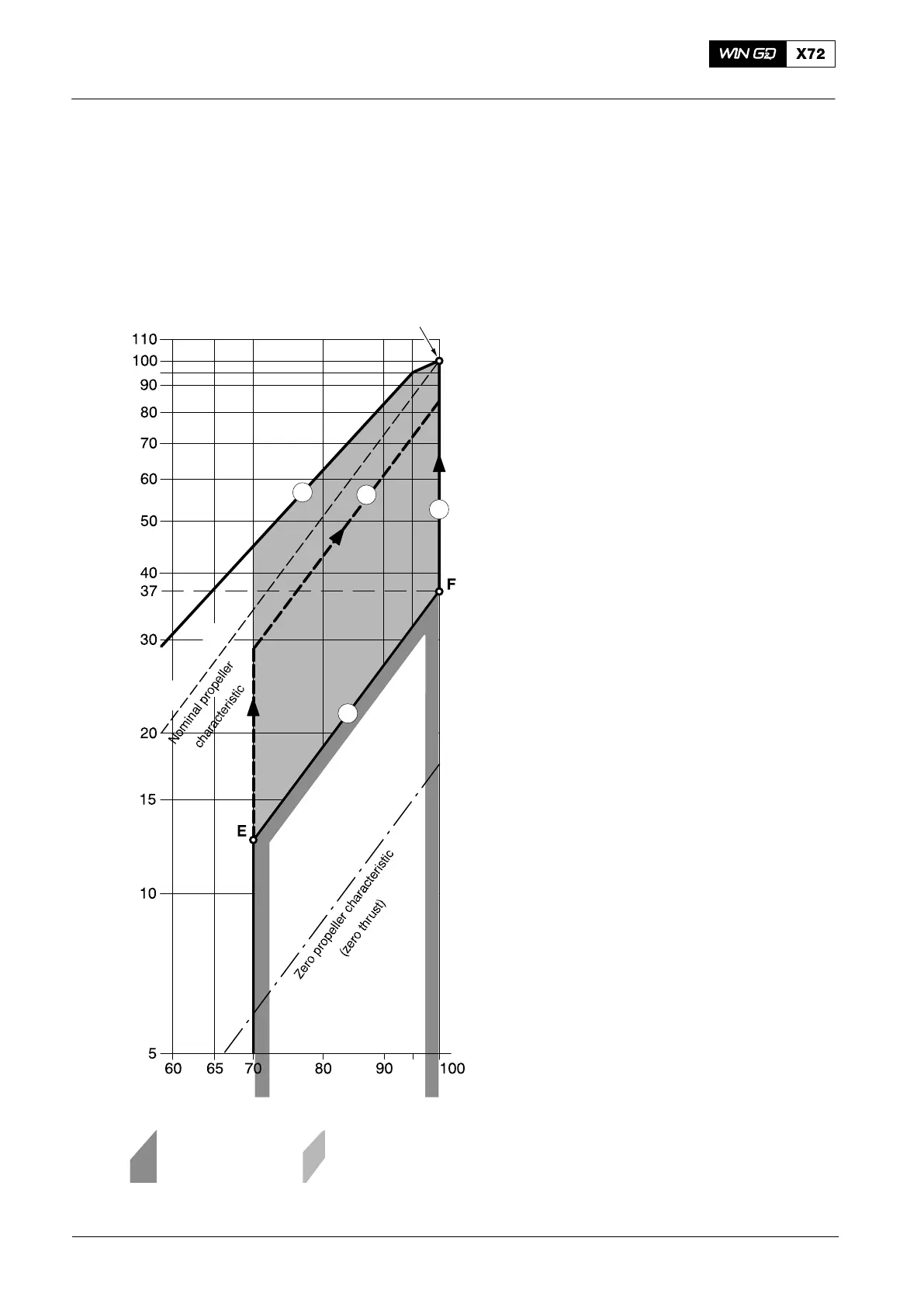
After engine start, the engine is operated at an idle speed of up to 70% of the rated
engine speed with zero pitch. From idle speed, the propeller pitch must be increased
with constant engine speed to the minimum at point E, the intersection with Line 9.
D Line 9 is the bottom load limit between
70% and 100% speed, with a pitch
position that at 100% speed, the
minimum power at point F is 37%. The
formula shown in paragraph 1 is used for
this calculation.
D Along Line 8 the power increase from
37% (point F) to 100% power (CMCR) at
100 % speed is the constant speed mode
for shaft generator operation
D Line 5 is the top load limit and relates to
the permitted torque limit.
D The area between 70% and 100% speed
and between Line 5 and Line 9 shows the
area that an engine with a CPP must be
operated.
Line 7 shows a typical combinator curve for
variable speed mode.
Maneuvering at maximum speed with low or
zero pitch is not permitted. Thus,
installations with main engine-driven
generators must have a frequency
converter when electrical power is to be
supplied (e.g. to thrusters) at constant
frequency during manoeuvring. As an
alternative, power from auxiliary engines
can be used for this purpose.
For test purposes, the engine can be
operated at rated speed and low load during
a one-time period of 15 minutes on the
testbed (e.g. NO
x
measurements) and 30
minutes during dock trials (e.g. shaft
generator adjustment) when there are an
authorized representatives of the engine
builder on board. More requests must be
agreed from Winterthur Gas & Diesel Ltd.
Fig. 2: Schematic Diagram of Speed / Power Relation (CPP)
2014
The Relation between Engine and Propeller
8
9
7
5
Engine power [% Rx]
CMCR (Rx)
Engine speed [% Rx]
Engine operation
is not permitted
Operate the engine
in this area when a