Maintenance1132−2/A1
Winterthur Gas & Diesel Ltd.
8/ 15
4. Main Bearing Shell −
Removal
4.1 Preparation
CAUTION
Damage Hazard: Do not
remove two adjacent main
bearing shells at the same
time. Damage to equipment
can occur.
1) Put the bracket 94141 (Fig. 12) on the
two main bearing girders (1) parallel to
the engine axis.
D Apply grease to the bottom of the
plates (4) to reduce the sliding
resistance.
2) Put a dial gauge in position on the
crankshaft in the vertical axis. Set the
dial gauge to zero.
3) Put a dial gauge in position on the
crankshaft in the horizontal axis. Set
the dial gauge to zero, see Fig. 13.
4) Put the two hydraulic rams 94936 on
the bracket 94141A.
5) Put the hydraulic ram 94936 under the
flywheel (1).
6) Connect the three hydraulic rams
94936 to the HP oil pump 94931, refer
to 9403−2.
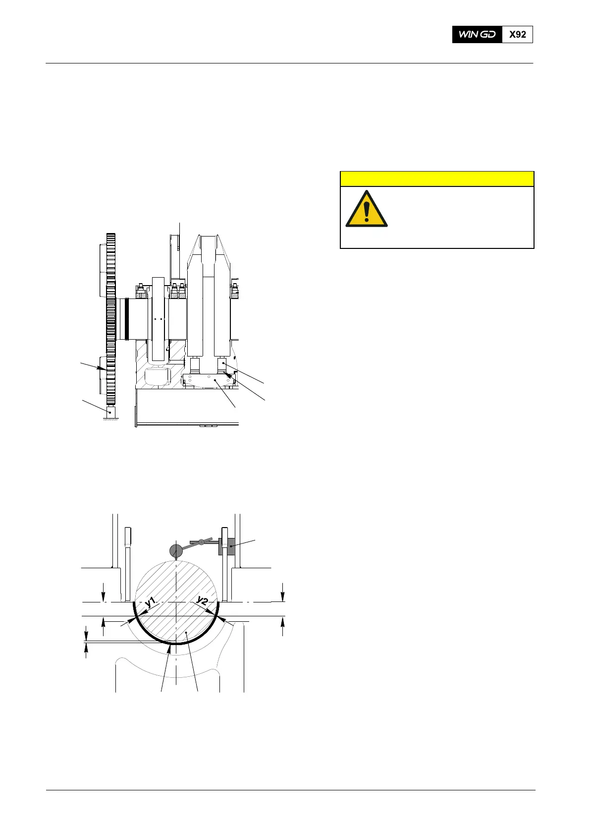
4.2 Crankshaft − Lift
1) Record the lateral clearances (y1) and
(y2), Fig.13) between the center of the
crankshaft (2) and the main bearing
shell (3) at approximately 50 mm below
the center line as shown.
2) Operate the HP oil pump 94931 to lift
the crankshaft (2) to the minimum
bearing clearance (0.3 mm).
3) Make sure that the horizontal
clearances on each side of crankshaft
between the crankshaft and the bearing
shell (y1), (y2) are the same.
4) If the clearances are the same, record
the pressure of the hydraulic pump.
5) Make sure that the pressure in the
hydraulic rams 94936 stays constant.
2015
Main Bearing − Removal and Installation
009.810/02
1
23
Fig. 12
Fig. 13
94936
94141
94936
WCH03015
1
0.3 mm
50 mm50 mm
4